OVERVIEW
The Objective of this project is to determine the stress and to predict the failure in the materials subjected to forces or increase the strength of the structure without increasing the weight of the rib.
The rib is made up of Aluminium and it is working parallel to the ground. I applied load of 10 KN in Z negative direction. The leading edge and tailing edge of the ribs has been fixed .
Then we do the prediction for the largest stresses on the ribs if the material is going to yield at these point.Besides, their location and value will help to make design improvements.
GEOMETRY
All the CAD Model was created and cleaned in CATIA V5. And the unimportant details were removed to help the simulation to converge.
All the CAD was finally saved in STEP format and uploaded to SimScale Workbench Geometry as shown in the Fig.1 and Fig.2 below
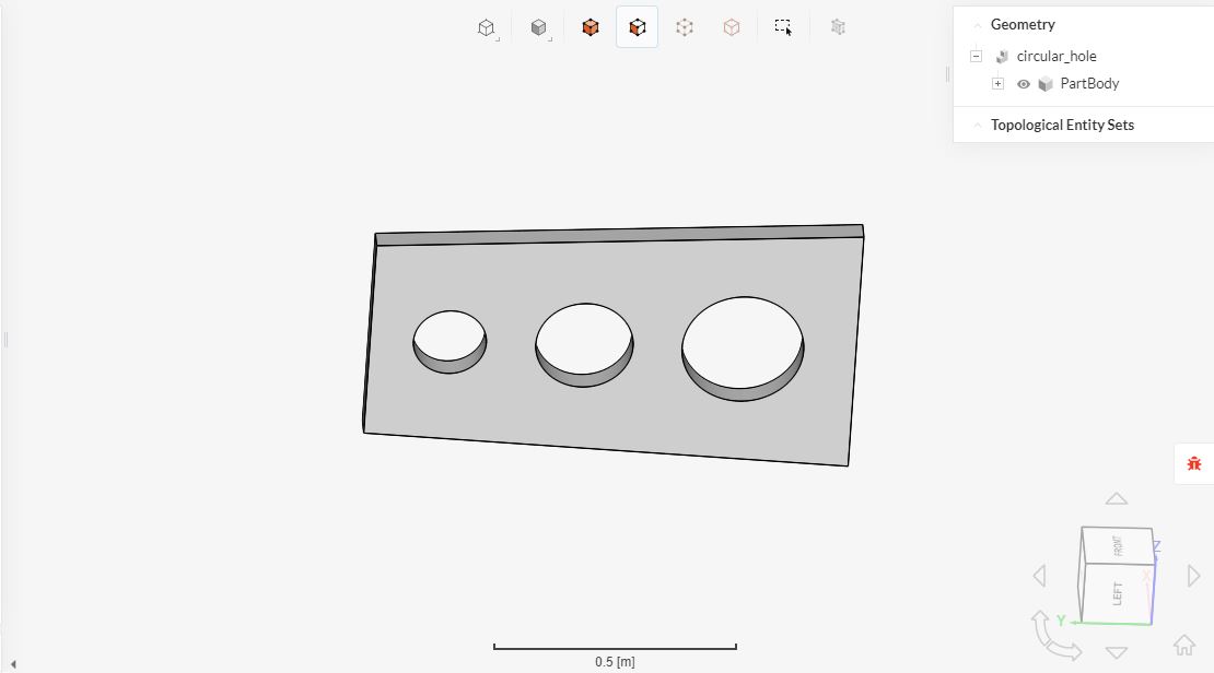
Fig.1: CAD Model of the rib with holes cut-out
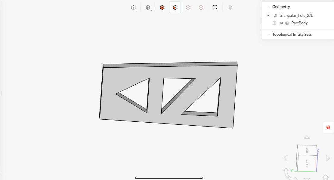
Fig.2: CAD Model of the rib with Triangles cut-out
MESH
The mesh algorithm chosen was Tet-Dominant one, and it was created by the automatic mesh sizing of the SimScale. The level of fineness chosen was moderate, enough resolution to obtained to identify the areas with higher stresses.
No refinement regions were created, so the resultant mesh is homogeneous to capture stresses and strains uniformly on all over the solid.
The mesh was run in parallel using 16 processor. The whole meshing took 2 minutes for both the cases. The mesh result has been shown below in Fig.3 and Fig.4.
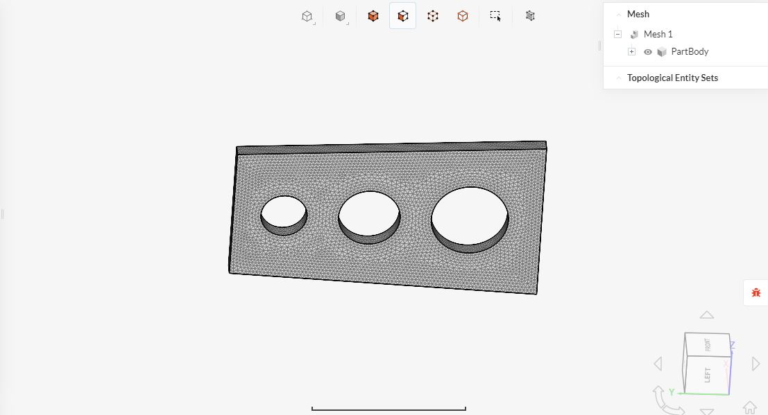
Fig.3: The CAD Model of the rib with hole cut-out after Meshing
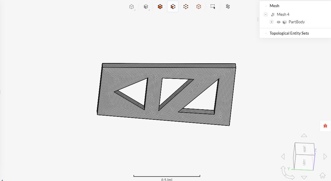
Fig.4: The CAD Model of the rib with triangles cut-out after Meshing
SIMULATION SETUP
Aluminium was chosen as the material for both the Model from SimScale Material Library.
Two Boundary Conditions were assigned:
- The Force in Z direction (-10 KN) was assigned to act on the front surface of the both of the CAD Model as shown below in Fig.5 and Fig.6 .
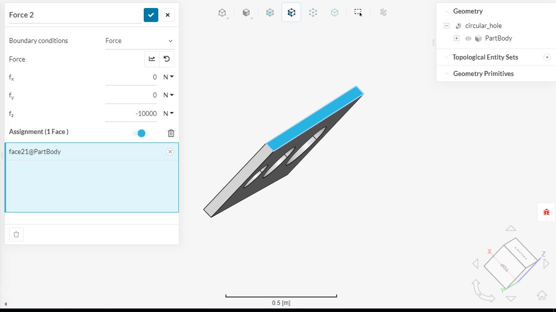
Fig.5: The assigned Force on the front surfaces of ribs with holes cut-out Model
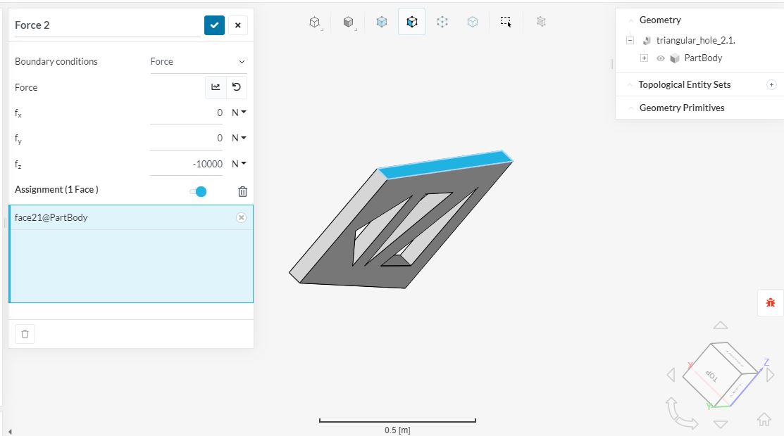
Fig.6: The assigned Force on the front surfaces of rib with triangles cut-out Model
- The top surface of both of the CAD Model has been assigned to be Fixed as shown in the Fig.7 and Fig.8 below.
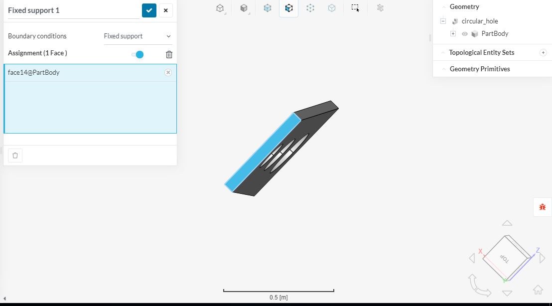
Fig.7: The Top surface of the rib with hole cut-out Model assigned to be Fixed
Fig.8: The top surface of the rib with triangle cut-out Model assigned to be Fixed
RESULTS
The Post-process result has been shown below for both the rib’s Model in Fig.9 and Fig.10
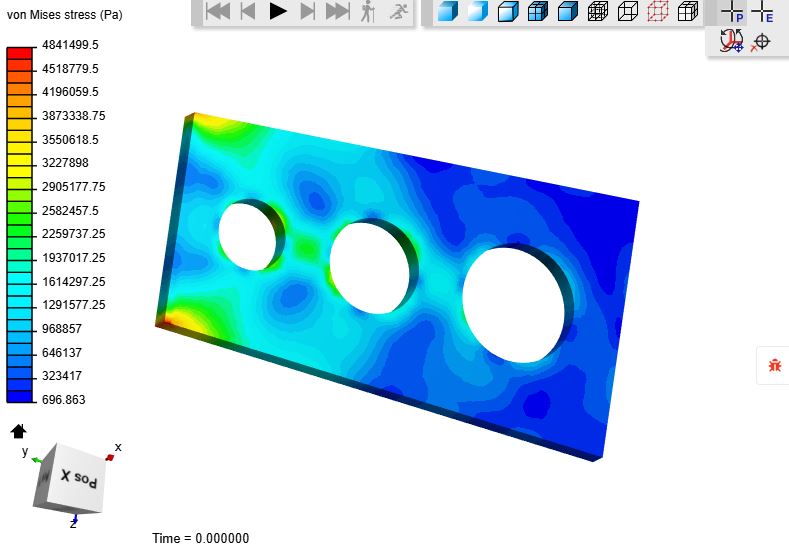
Fig.9: The Post Process Results of the simulation for the rib with holes cut-out Model in von Mises Stress 
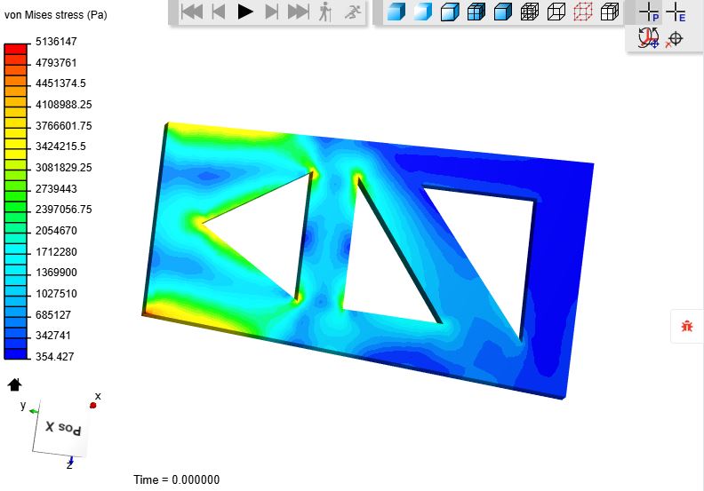
Fig.10: The Post Process Results of the simulation for the rib with Triangles cut-out Model in von Mises Stress 
CONCLUSION
After comparing the results of both of the Model’s stress value, we came to the conclusion that if we use rib with holes cut-out instead of rib with triangles cut-out we can increase the strength of rib without increasing its weight as well as the strength of the wing which is an important part of the Aircraft.
 I have moved this topic to “projects” though - the standard procedure would be to create a project add a small comment under your project inside the Dashboard and then continue editing this in the forum which will automatically post it inside the Projects section.