It’s Euro Cup 2016 time which brings to mind an interesting phenomenon…Have you ever seen a football player gracefully curve a ball into the goal? Why does this happen?
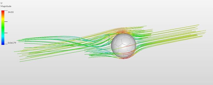
It’s the Magnus Effect!
Named after the German physicist H.G. Magnus who experimentally investigated this effect in 1853, the Magnus effect is the phenomenon of the generation of a side-wise force on a spinning spherical solid in a fluid. Read more…[1]
Let’s create a simulation to show the Magnus Effect in action.
Project Link : https://www.simscale.com/workbench?publiclink=f318b499-259b-4f37-be1d-8990955443a7
Click on this link to directly import the project with the football into your workspace.
Then follow the steps below for setting up the simulation. .
Meshing
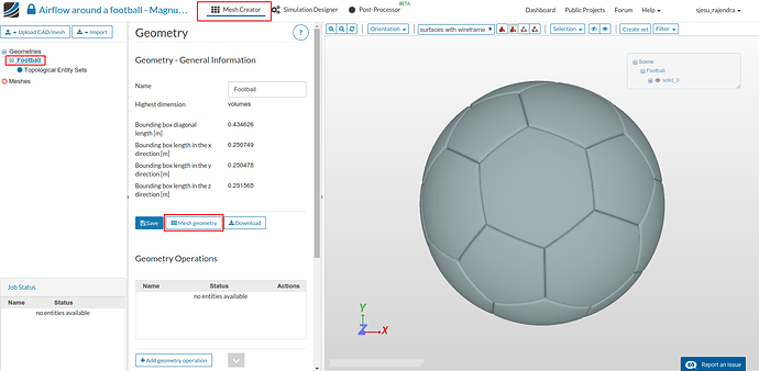
- In the ‘Mesh Creator’ tab, click on the geometry ‘Football’
- Then, click on ‘Mesh geometry’ button in the options panel.
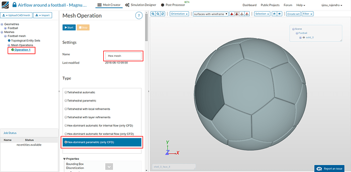
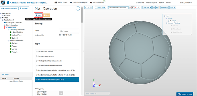
- A new mesh operation will be created - rename it as ‘Hex mesh’. Select the last option ‘Hex-dominant parametric (only CFD)’.
-
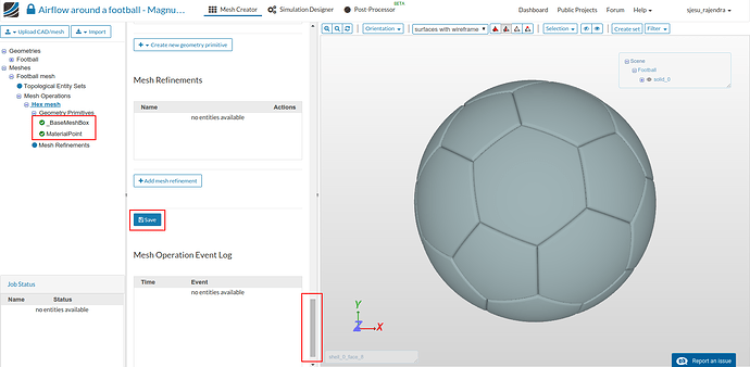
Now, scroll down to the bottom and click on ‘Save’. Once saved, new entries will automatically appear under ‘Geometry primitives’ with recommended values. Please note that you have to click on Save every time a change has been done to the properties.
-
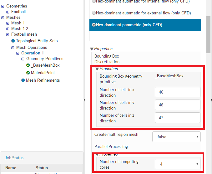
Scroll down and check that your settings are as follows
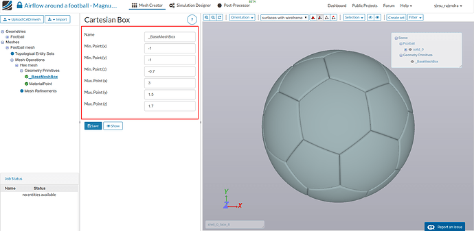
- Now you will see two new items in the project tree: the BaseMeshBox and Material Point
- Please make sure the BaseMeshBox and Material Point have the following coordinates.
Geometry primitive
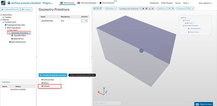
- Next we add a new primitive to include region refinements. It is done by clicking on Geometry primitive and selecting Create new geometry primitive.
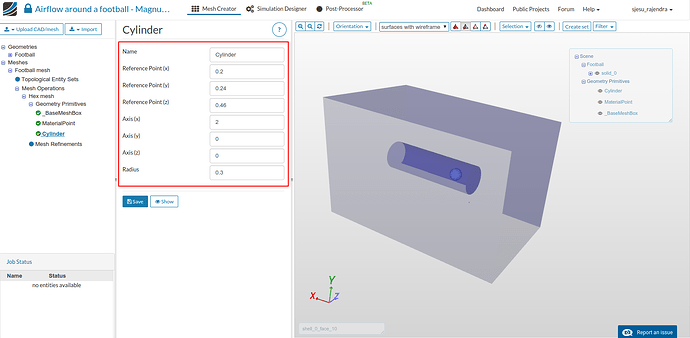
- Add a new cylinder with the following properties.
Mesh refinements
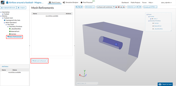
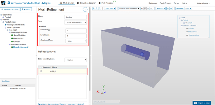
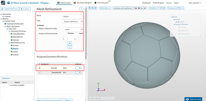
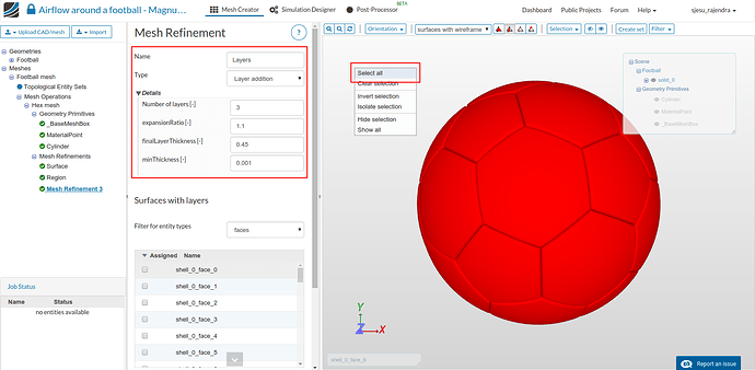
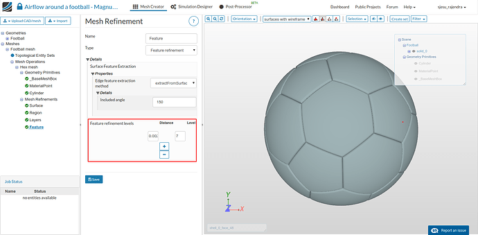
- Next, we will create 4 ‘Mesh refinements’ by clicking on ‘Add mesh refinement’ in the options panel.
- Add a ‘Surface refinement’ by setting up the options as shown below and clicking on ‘save’.
- Add a ‘Region refinement’ by setting up the options as shown below and clicking on ‘save’.
- Add a ‘Layer refinement’ by setting up the options as shown below. After selecting all the faces from the viewer click on Add selection from viewer to select the entities and select ‘Save’.
- Add a ‘Feature refinement’ to refine the edges by setting up the options as shown below and clicking on ‘save’. Use a ‘Distance’ of 0.002 and ‘Level’ of 7
- Now, click back on ‘hex-dominant’ and click on ‘Start’ button to begin the meshing process. The process will begin and the status can be viewed in the lower left corner under ‘Job Status’.
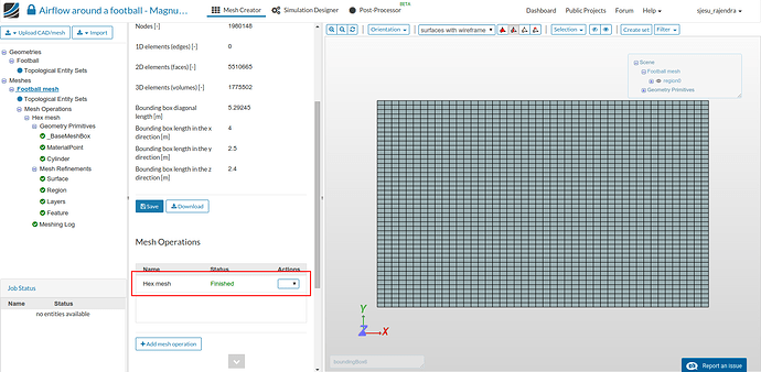
The meshing process will take less than 25 minutes to finish. The mesh will automatically load in the viewer once done.
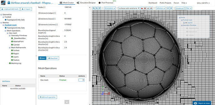
A cross-section across the domain is as shown. The layers and refinements can be seen as defined.
Simulation Setup
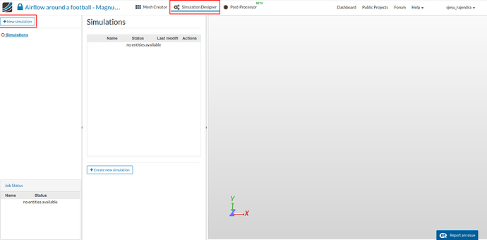
Now to setup the simulation, switch to the ‘Simulation Designer’ tab.
- Click on ‘Create new simulation’ in the options panel, give it a relevant name and click ‘Create’
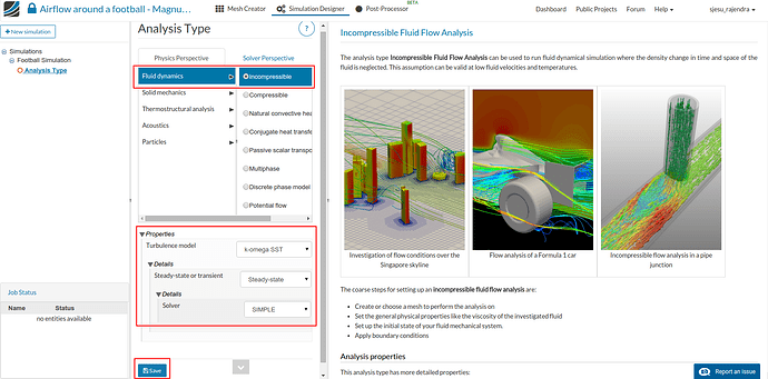
- Select the ‘Analysis Type’ options as shown to create an ‘Incompressible steady-state’ with ‘K-omega SST’ turbulence model and click on ‘Save’.
- After saving, the simulation tree will be generated. We will setup the essential entries required for this simulation.
Domain
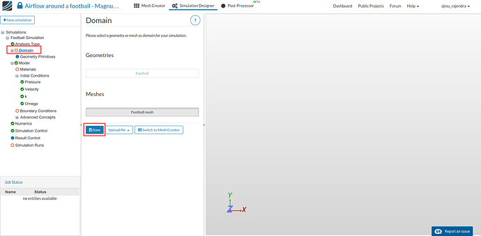
- First is ‘Domain’, where we select the ‘Mesh’. Click on ‘Domain’ and select the available mesh and then on ‘Save’. The selected mesh will automatically load in the viewer.
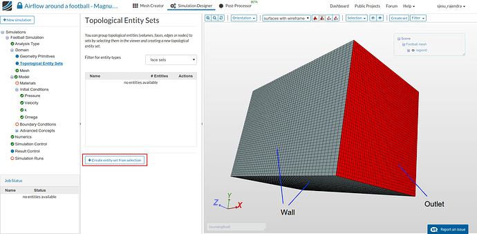
- Click on ‘Topological Entity Sets’ to name the boundaries of our domain. The boundaries are as shown in the following figures. It has an Inlet and an Outlet surface, the other 4 outer boundaries are marked as walls.
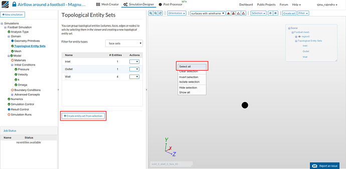
- Now hide all the outer walls (since we have already named them) and right click in the viewer. Select all the faces and assign it as Ball. Now we can define any property to the ball by selecting this entity.
Model
Under model comes the ‘Materials’, ‘Initial conditions’ and the ‘Boundary conditions’. We will go through them one by one.
Materials
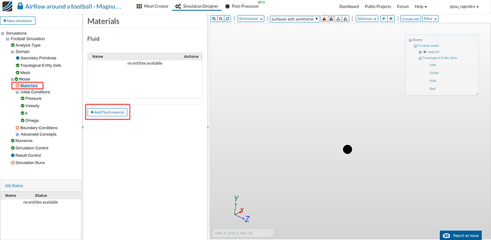
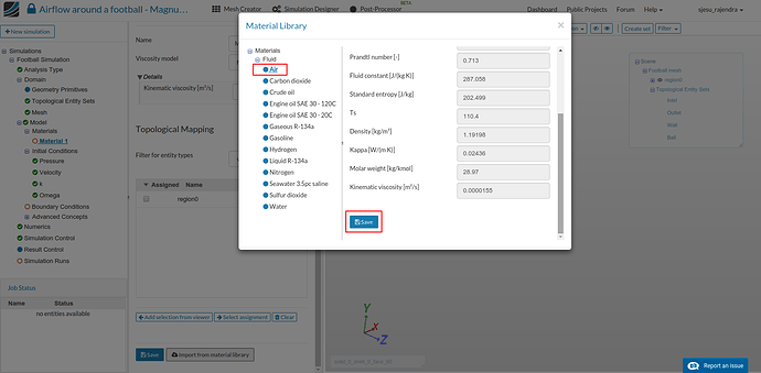
- Click on ‘Fluid’ and then on ‘Add Fluid material’ in the options panel.
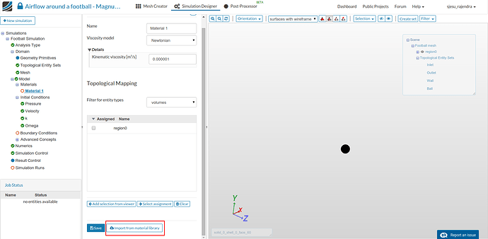
- Scroll down to the bottom and click on ‘Import from material library’
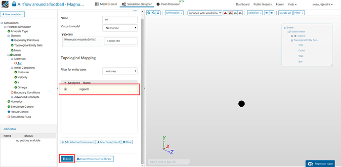
- Select ‘Air’ and click on ‘Save’
- From the ‘Topological Mapping’ list select ‘region0’ and click ‘Save’ to assign the fluid material to this mesh region.
Initial Conditions
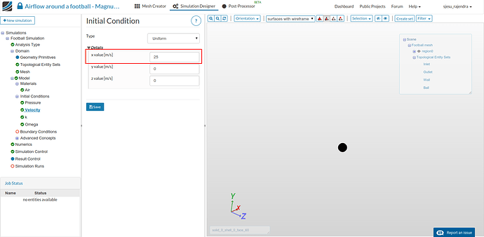
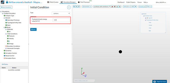
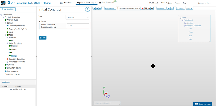
For the ‘Initial Conditions’ the changes are made in entries an shown in the following figures. Please click the Save button every time to save the properties.
Boundary Conditions
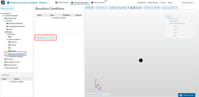
- Now add the boundary conditions to the setup. In the sub-tree click Boundary Conditions and select Add boundary condition
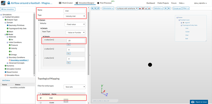
Inlet
- Add a new ‘Velocity Inlet’ boundary condition for ‘Inlet’ BC. This is defined as Fixed value ‘Velocity’ with a value in the x direction of 25 m/s. Click Save
Outlet
- Add a new boundary condition for ‘Outlet’ BC. Define the ‘Outlet’ condition with Pressure outlet with default value. Click Save.
Ambient
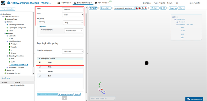
- Add a new boundary condition for the outer walls called as ‘Ambient’. These walls are defined with a ‘Slip’ condition to represent the surrounding.
Ball
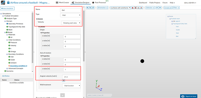
- Now you can define the spinning condition for the ball, which actually defines the Magnus effect. This is done by giving a rotation to the ball, with an angular velocity of 31.4 rad/s. Please note the negative symbol of angular velocity to account for the direction of rotation.
Numerics
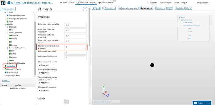
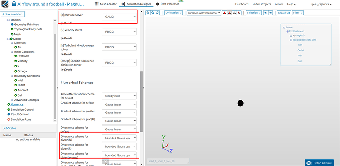
- The following numerics are changed for obtaining a converged solution. Click on Save button.
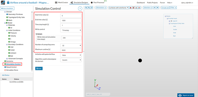
Simulation Control
- Click on Simulation Control in the sub-tree and enter the end time as 1000 s with time step of 1.
- Click on Details below write control and enter 250. Select the number of cores as 32 and enter 5000 as maximum run time. Click Save
Result Control
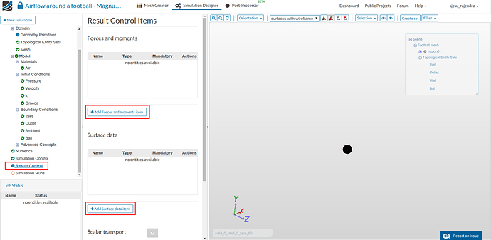
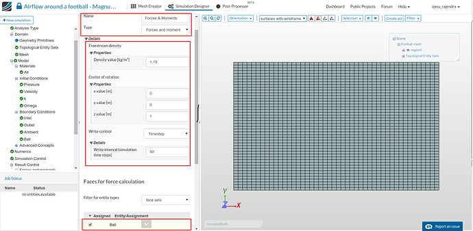
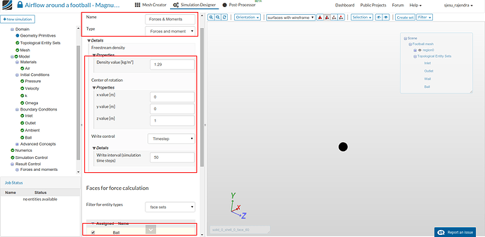
- We can create some result controls to get additional information out of the simulation. This can be done by selecting Result control in the sub-tree and ‘Add forces and moments item’.
- The following setting can be maintained to obtain forces and moments acting on the ‘Ball’.
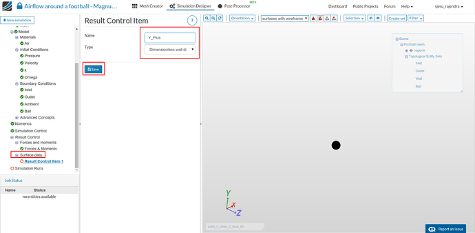
- Again click on Result control and select ‘Add surface data item’. Select as shown below to obtain the y plus values.
Create New Simulation Run
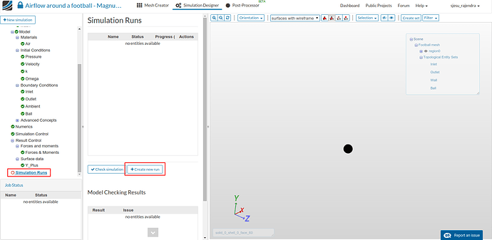
- Click Simluation Runs on the sub-tree and select Create new run. Click on OK
- Click on Run 1 and then on Start button. This starts computing the simulation run.
The simulation runs for 30 mins approximately. Once it is done the status changes to Finished.
> Click here for Part 2 for the Post-Processing Tutorial
References




 Isn’t SU2 a compressible code?