Hi,
I am a new user of SimScale and I was trying our some simple problems I wanted to figure out how large assemblies are analysed on SimScale more specifically how to define the connections/joints between the parts of the assembly.
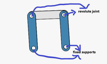
So I modeled a simple assembly shown below

I gave cyclic symmetry for the revolute joints and fixed the other two supports.
After running, solver error message comes up always.
Am i doing anything wrong ? Is there any other way to define revolute joints ?
Thanks and Regards,
Vignesh
Hi @VigneshKC,
Can you share a link to your project so we can take a look at it?
Thanks,
Christopher
Hi @cjquijano ,
See above the link of the project.
Thanks,
Vignesh
Sorry for the late response @VigneshKC!
@ggiraldo, could you give it a quick spin if you have the time? Would be awesome!
Cheers,
Jousef
1 Like
Hi @VigneshKC,
Sorry for the late response.
Imade a copy of your project here.
The Cyclic Symmetry boundary condition is used if you are modeling a sector of a revolved model such as a fan disk or a pressure vessel. What you want to use in this case is the Sliding Boundary condition. This works well for linear problems with small motion. I also had to constrain the top bar in teh Z-direction.
Please take a look and let me know if you have any questions.
Christopher
3 Likes
Hi @cjquijano
Thanks a lot for your response. I will certainly explore more to get a better understanding.
Thanks and Regards,
Vignesh
1 Like
