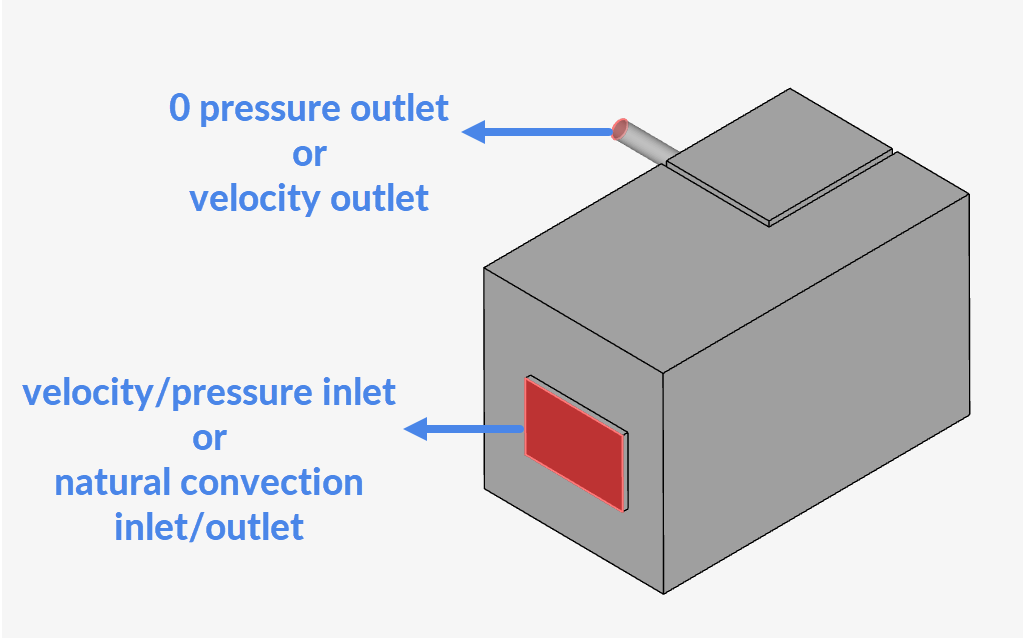
With this simulation i am trying to analyse the air flow pattern and ventilation rate in a studio apartment by including the exhaust air from cooking. The goal is to set the inlet air flow through windows and to extract it through the bathroom exhaust because the apartment has an open kitchen without kitchen hood so this simulation is about finding alternate option for kitchen exhaust which will be vented through the mesh/hole above the kitchen wall and then extracted by bathroom exhaust to outdoors through ducts.
i am adding the link to my workbench
Hi @dEEpAk135, thanks for posting on the forum and welcome to the SimScale Community 
I think you have two options, namely:
- To set the window as a velocity/pressure inlet and the exhaust duct as a velocity or 0 pressure outlet
- To set the window as a natural convection inlet/outlet and the exhaust duct (again) as a velocity or 0 pressure outlet
Best,
Igor
Hi Igor, this step which you have mentioned is the parameters under simulations right ? but shouldn’t i define the rotating zones for the exhaust before fixing these inlet/outlet parameters or will it be set as default ?
Additionally, how to include the ktichen exhaust in the air stream which will be extracted by the bathroom exhaust ?
Thank You
Deepak
Hi @dEEpAk135,
The rotating zone should be used if you had the actual fan modeled and wanted to observe, let’s say, the actual impact of the blades’ rotation on the fluid flow. As this is not your case, you should only use an outlet to indicate the flow is headed in that direction.
If the objective of the simulation is observing whether the air from the kitchen would be pulled by the exhaust equipment in the bathroom, the simulation should show this by itself. As the window is the only way for the fluid to flow through to get to the outlet, the flow should be naturally directed towards it.
Best,
Igor
1 Like
Hi Igor,
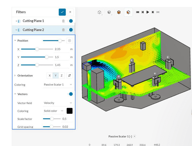
please consider the simulation result that i attached. This is reference simulation as part of the simscale tutorial.
as i understand this simulation result, the indication of air from the ventilator is supplied throughout the meeting room. The colour grading indication of Temperature ranges are also present.
so i am expecting a similar result of extracting false/stale air from cooking through the vents/openings and finally through the bathroom exhaust towards outside/ducts.
an indication of temperature range similar to the attached simulation is also necessary.
and regarding rotating zones, inorder to get the air/fluid flow towards outside through the exhaust would it be needed ? i.e., the idea is to pictorially and analytically demonstrate the effect of bathroom exhaust in sucking out the humid air inside.
Let me summarize once again, i need to obtain two type of results
- the simulation indicating outward air flow through exhaust( window closed, and say the cooking is going on so there will dense air t´which should be removed/extracted)
-the second one would be the window opened case! (where the air flows through the window and flows out through exhaust in the bathroom).
The exhaust will be working continiously.
Thank You
Deepak
Hi @dEEpAk135
Your objective is to observe airflow patterns, not the fan design. All fans are designed to create a pressure differential, which in turn drives airflow either inwards or outwards. However, boundary conditions can greatly simplify this if you don’t need to explicitly model the flow patterns and turbulence in the fan’s near-region. My advice is to thoroughly study the role of boundary conditions in numerical simulations.
Regarding your other question about exhaust air, again, it’s essential to understand boundary conditions and their various definitions. It’s a complex topic, as you can either impose a velocity flow (inwards or outwards) or set a pressure differential, which will then drive the flow.
Lastly, what you’re observing in the tutorial isn’t a temperature field, but the transport of a passive scalar. This represents the diffusion and convection of a “passive” tracer substance that does not interact with the flow but is carried within the domain.
1 Like
Hi @jairogut
Thank you for the reply.
Yes, as you said my objective is to observe the air flow pattern inside the apartment, and also to analyse the effect of bathroom exhaust in taking the air outwards(i.e., total air volume of apartment).
But, as i said before the inclusion/indication of exhaust air from cooking in the air stream is also important to my study, beacuse it also the part of research goal to find out the level of ventilation rate which is possible through this technic/mechanism or design.
This is the link to my simulation, could you explain how to interpret these results and does this result help me to support my research goal ?
Thank You
Deepak
Hi @dEEpAk135,
When it comes to the interpretation of the results, unfortunately we can’t comment on anything in specific as this would be a task for someone more familiar with the problem such as yourself. What you can do is try and compare them to physical expectations or similar problems.
However, one thing we can help with is to try and see if - on the simulation side of things and assuming that the setup is in line with physical conditions - everything is in order. One result to look at is the convergence and stability of your model, and here’s a resource from our side on that topic:
Another good option to help interpreting the results is getting familiar with the post-processor. We also have a tutorial on that which might be helpful:
Best,
Igor

