Pictures and Documentation of New Meshing Strategy
Trial 6 - Aero 2 - Mesh QT 6
| Total Cell Count | 14.2m |
|---|---|
| Time | 152min |
| Illegal Cells | 6524 |
| Checking faces in error : |
**non-orthogonality > 70  degrees                        : 6355**
faces with concavity > 80  degrees                     : 0
faces with skewness > 4   (internal) or 20  (boundary) : 0
faces with interpolation weights (0..1)  < 0.02        : 0
faces with volume ratio of neighbour cells < 0.01      : 5
faces with face twist < 0.01                           : 11
faces on cells with determinant < 0.001                : 0
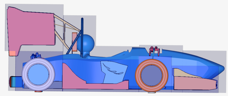
1. New Cartesian boxes
Cartesian boxes are now setup to encompass the geometry as closely as possible to reduce total cell count
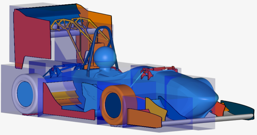
Zone 1 - Nose
Zone 2 - Front Suspension
Zone 3 - Driver area
Zone 4 - Rear of mono
Zone 5 - Front Wing
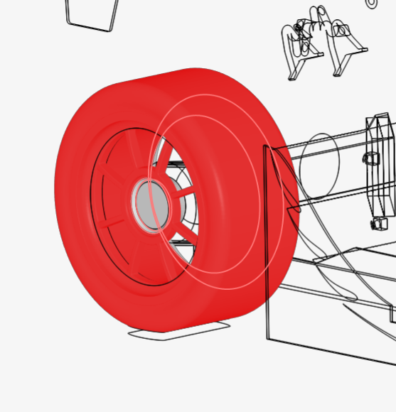
Zone 6 - Front Tire
Zone 7 - Diffuser
Zone 8 - Rear Tire
Zone 9 - Pre-Rear wing
Zone 10 - Rear wing
Zone 11 - Cell reduction box
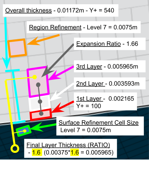
2. New Boundary layer settings based on Level 7 & Level 8 Y+ = 540
Level 7
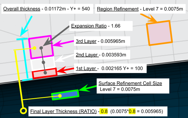
Level 8
3. Needed improvements
Geometries
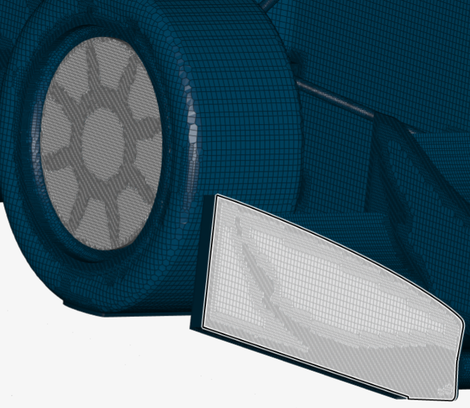
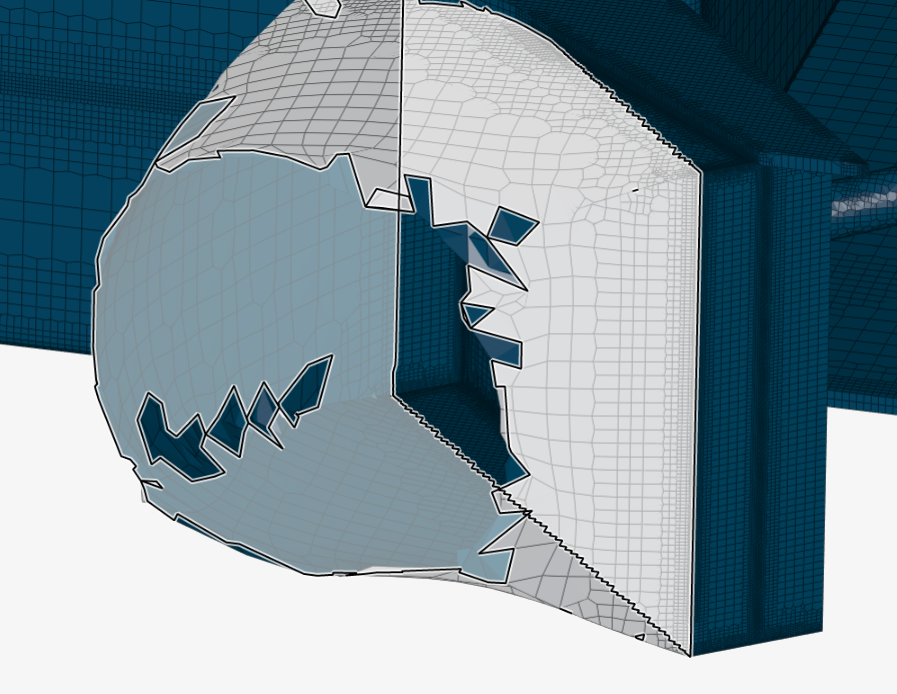
- Split wheel and rim geometry
Outer wheel surface and spokes share same face selection
-
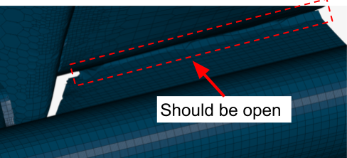
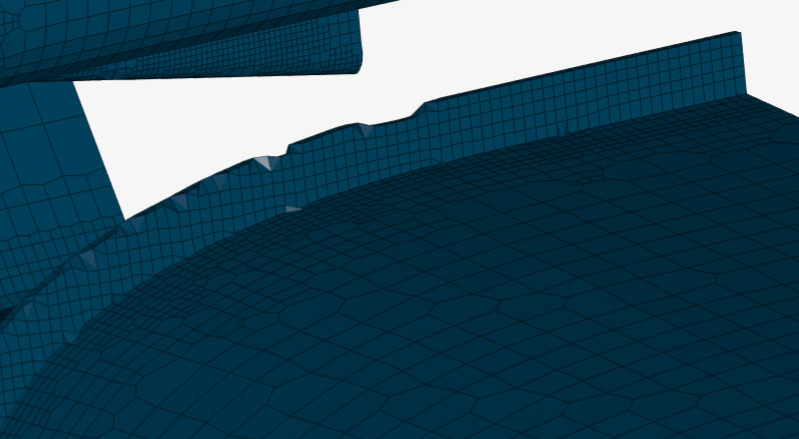
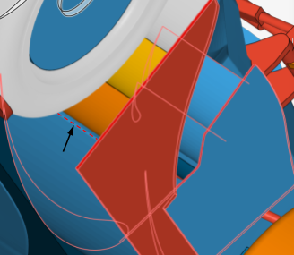
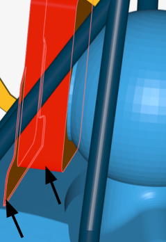
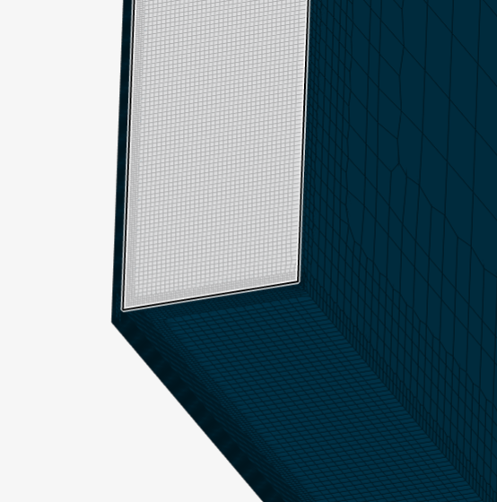
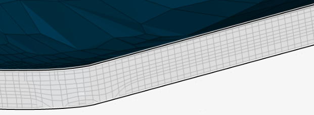
Shorten middle of front main wing (mesh attaches to nose)
Mesh has fused to nose so air cannot pass through.
-
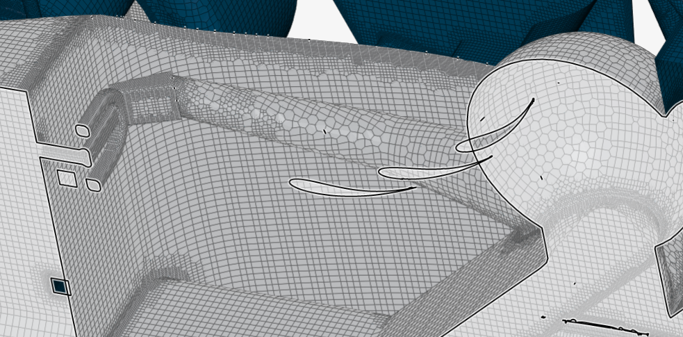
Split foot pedal cover face from mono
This is the smallest surface attached to the mono other then the dummy area. This results in a split level refinement being needed which is not optimal
-
Split driver dummy area from main mono
The necessary smaller surface refinements of this area should be separate to the mono, boundary layer dependent surface.
-
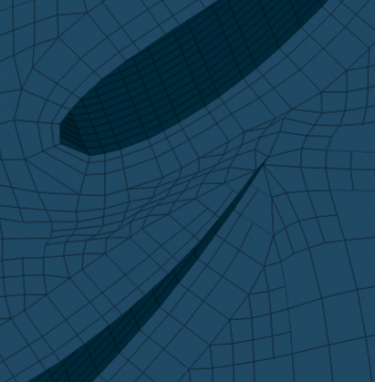
Diffuser trailing edge cannot be selected
The main diffuser profile has no trailing edge face to select. These must be split
-
Headrest small edge face and side pillow have same face selection
The small edge face and larger headrest side face should be split to reduce cell size
New Mesh Changes
- Mesh size way to fine on rear wing holder main face, smaller side faces, and lateral stabilizing beams.
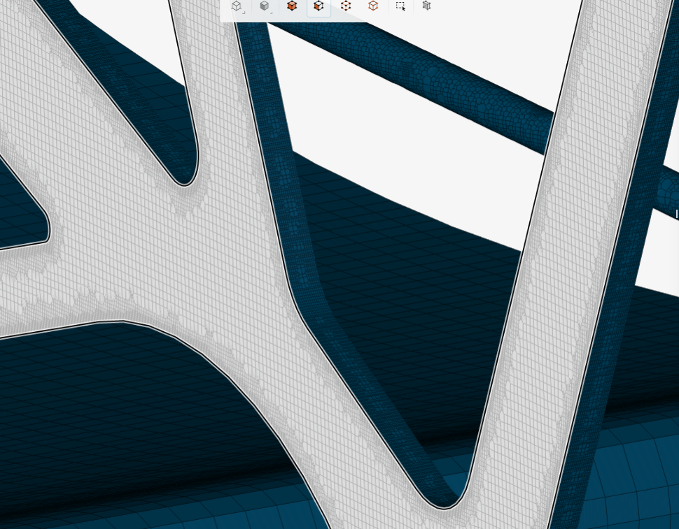
- Mesh reduction on faces such as the MRF zones are getting “print through” from neighboring geometry. This is seen on MRF zone spokes and front endplate wing profile.
-
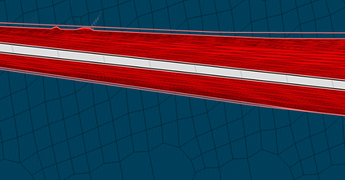
Front wing outer endplate gurney flaps cell size too small
-
Rear wing element gurney flap cell size too small
!
-
Radiator exhaust shroud mesh too coarse. Jagged edges
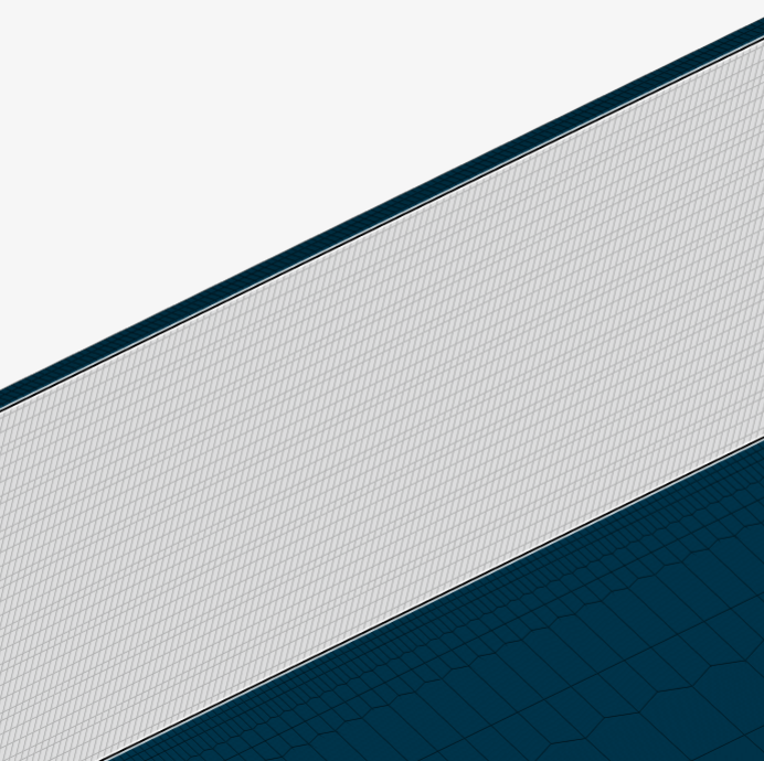
- Trailing edges were not meshed however most were converged with cells from the top and bottom of the wing surface. An exception is the front main wing trailing edge which was meshed.
- Contact patch cell size too small
- Trailing edge of wings, boundary layers not created.
By making these changes then most of the model can be separated into small small faced - high refinement level areas, and the larger cell size areas like the mono. Also unnecessarily small cell refinement areas can be improved.