Optimizing mesh quality and Y+ layer formation on an FSAE car

Hi everyone

I will be documenting and experimenting on how to get the optimal mesh quality for an FSAE half simulation (and eventually full car) with focus on important parameters such as:

  • Total mesh cell count - (dont want too many core hours / memory failure with 32 processors)
  • Y+ Layer formation - measuring in log-law region 30<Y+<300 with first layer thickness = 30
  • Illegal Cell count - The lower the better but not at the expense of omitting layers
  • Overall mesh quality and accuracy - Optimization of mesh controls (Castellated mesh, Snap, Layer adding, mesh quality)

Link to project:
https://www.simscale.com/workbench/?pid=3437970283570097560&mi=spec%3A423efb47-258e-4366-9d9c-cb7847dea6ab%2Cservice%3AMESHING%2Cstrategy%3A69&ps=geometryPrimitives%2F3&sh=9

I hope that some of the power users - at least the ones i know - can help me with this thread as I am surely not alone in having little knowledge in how to manipulate the controls and settings to get the mesh i am looking for.
@jousefm @Get_Barried @DaleKramer @Edoardo @Kai_himself @Retsam

  1. The first topic (more like question ) i would like to cover is for the optimal Y+ layer creation.

I have read through the documentation provided by Simscale for hex-parametric controls. and Y+ a few times over already and have also researched and determined that measuring the boundary layer in the log-law region is appropriate for an FSAE simulation.

My goal for this first topic is to optimize the first cell layer thickness so that it is ar the necessary Y+ = 30 throughout all surfaces in the model. This will ensure that the viscous sub layer region is being accurately “averaged”.

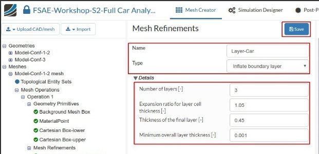
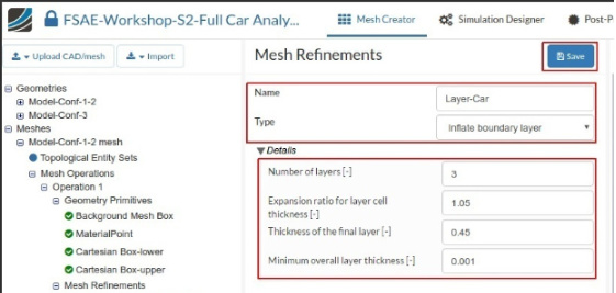
Using the inflate boundary layer settings provided by the FSAE Step-by-Step Tutorial: Homework of Session 2
image

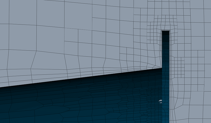
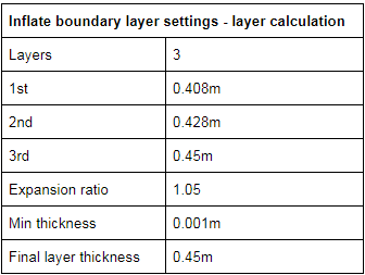
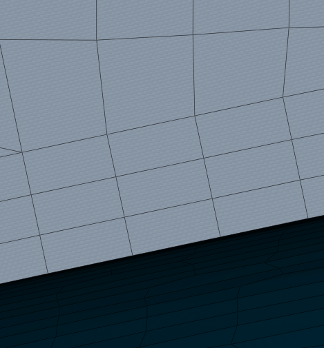
I created an boundary layer mesh shown below. While I understand that having an expansion ration of only 1.05 will result in a low difference in size between all three cells, a calculation of the first layer thickness (shown in second pic) results in thickness that does not seem right.

image

This is where I start to get confused because after reading about Y+ I learned that the first layer size can be calculated based on the desired Y+ distance. In this case I wanted 30. I had found 2 different calculators yet the results from each are different with the same inputs.

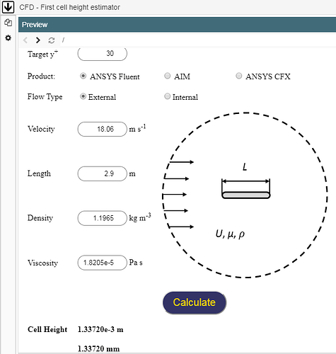
First Y+ Calculator Tips & Tricks: Estimating the First Cell Height for correct Y+ | Computational Fluid Dynamics (CFD) Blog – LEAP Australia & New Zealand


Using this calculator the estimated first cell size is 1.33720e-3m or 0.00137m

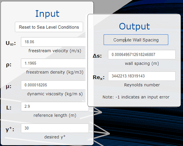
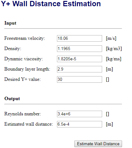
Second Y+ Calculator CFD Online - Y-Plus Wall Distance Estimation
image
Using this calculator the estimated first cell size is 6.5e-4m or 0.00065m

These are two very different results, and to make it worse they are both very different from the suggested first layer thickness provided in the FSAE tutorial.

Calculator 1 = 0.00137m
Calculator 2 = 0.00065m
Tutorial = 0.408m

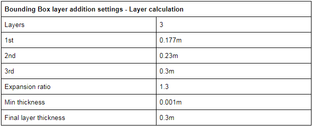
However, upon seeing the good layer formation of the bounding box layer addition settings (which is pretty much an inflated boundary layer but for the moving floor), these settings were used for the car boundary layer.
image
Which resulted in cells forming as shown below
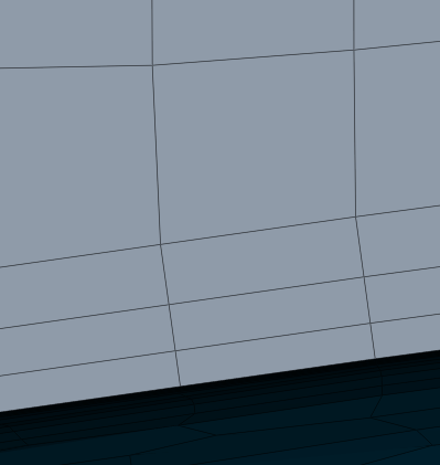
These settings result in a first layer thickness that is smaller but still not near to the Y+ of 30 of both calculators.

Calculator 1 = 0.00137m
Calculator 2 = 0.00065m
New boundary layer settings = 0.177m

Can anyone explain or verify the following questions

  1. What should the first layer thickness be for a Y+ of 30 in my situation?
  2. Are any of my calculator inputs incorrect which leads me to believe that the tutorial first layer size of 0.408m is too large compared to the calculators?
  3. Do you recommend investing so much effort into a correct Y+ cell size or is this goal unimportant for simulation accuracy in an FSAE car?

Many thanks to anyone with help or input. I will be adding post in the future to address the other goals of this thread. Thanks!

Dan
4 Likes

At first glance, this looks incredible - thanks a ton Dan! :slight_smile:

If I find the time I will put this into LaTeX and make it accessible to other people in PDF format. But for now I would agree that we optimize some points and make sure to cover everything properly.

@DaleKramer @Retsam, you are pros here, feel free to add your expertise and (especially you Dale) see if there is some synergetic effect with your y+ studies from the past (which I am sure there definitely is)! :slight_smile:

Cheers and thanks again Dan!

Jousef

Quickly I see that the 1.33mm is labeled Cell Height whereas the cfd-online calculator give center of cell distance, so there seems no discrepancy there… 1st layer thickness = 2 times cell center distance

As far as tutorial values, you would have to show us where it is derived…

Yes it is worth getting it right… (I suggest aiming for y+50 to get a wall function mesh, then, if needed, tweek after you see a y+ surface mapping from a converged sim run)

Hi there!

Personally I use PointWise calculator:

Results match your #2 calculator.
After first, second and third layer thickness calculation, you need to add them all to get to Final Layer thickness.

In that case you will have:

1: 0.65 mm
2: 0.6825 mm
3: 0.716625 mm


Sum: 2.049125. This is your Final Layer thickness in mm.

In you tables and text I see m instead of mm: possibly a mistake.

Now, when using Y+ calculators, please pay attention to viscosity: some use kinetic others dynamic. Dynamic viscosity = kinetic viscosity x air density, so beware.

Cheers,

Retsam

Dale, thanks for the input. I also agree that getting this right is important. The tutorial values i shared in the post but maybe i shouldn’t have called it Tutorial values if that was confusing. this is what i was talking about
Using the inflate boundary layer settings provided by the FSAE Step-by-Step Tutorial: Homework of Session 2.

This link is step by step instructions for setting up a half car simulation of an FSAE car for the Simscale Academy. In it are all suggested settings and refinements needed to complete a mesh and simulation. It is meant as a tutorial for students new to Simscale that are trying to learn CFD for FSAE purposes.

Here is the suggested inflate boundary layer settings from this Tutorial

image

Which results in this first layer thickness - 0.408m

image

I agree that setting to Y+ of 50 to get a stable boundary layer then tuning from there is a great idea. I will do that for sure.

Dan

I do not see the values that were used in a y+ calculator that resulted in those parameter values for that mesh refinement…

EDIT (My guess is that relative layering is turned on and that the 0.45 is a ratio between final BL layer thickness and the local volume mesh cell size next to the final BL layer…)

Beware, all meshing algorithms are not the same wrt parameter names and their meanings/units ! (even some names and their meanings/units do not even change when you change your mesh from ‘relative’ to ‘absolute’ layering control, be prepared for some frustration if you come across things like that…)

The only refreshing part of the tedious layering process for a specific y+, is that there is a solid metric that can be used to see if you got what you think you asked for… That is, being able to view a y+ surface mapping from the results of a converged sim (don’t forget to add a results item for y+, or you can not see that mapping in your results :wink: )…

I am not familiar with the meshing algorithm which those Mesh Refinements are used for??

I don’t think it is HEX parametric, is it? Or it is from a much earlier version of the SimScale UI for HEX parametric?

Regardless, the calculators do work (and should be used with the caveats suggested) and I would not worry much about that ‘tutorial’…

Thanks Retsam!

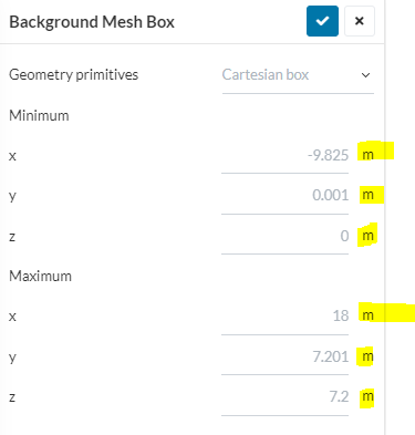
I used meters (m) and not millimeters (mm) because i assume Simscale needs to have these numbers in meters (m). I am assuming this because all inputs for sizing (bounding box, material point, Cartesian boxes), as well as uploading the geometry is all done with meters.

image

However i could be completely wrong on this, which would explain why the value of the tutorial first layer thickness and the calculators are so far apart.

Right before making the original post i noticed that the second calculator requires dynamic viscosity and the first calculator just says viscosity. So i will pay close attention to that in the future. I will also use your calculator to have three different sources to compare haha

Dan

  1. I am also unaware of where the values from the tutorial came from.

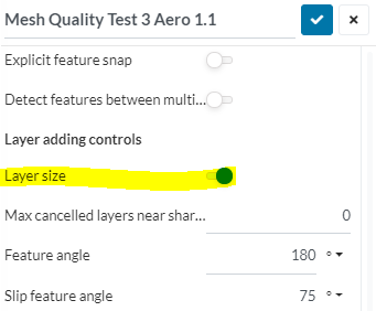
  2. I am very interested in experimenting with the layering size option (i assume thats what you mean with relative and absolute layering control) shown below
    image

  3. I have read about Y+ surface mapping but every post about this topic says that you need to export to Paraview to see it. Is it possible view within Simscale or must it just be selected in the results control, as you said, so that it is recorded in the simulation for Paraview?

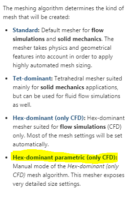
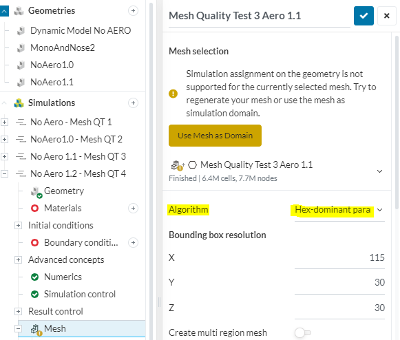
  4. These are the choices for algorithm selection, it is called Hex-dominant parametric ( if this is what u were refering to)
    image
    image

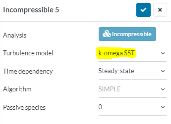
If you meant turbulence model, it is K- omega SST.
image

Thanks for the reply,

Dan

  1. RE: Tutorial - See my previous posts (EDIT) before you posted yours, I am virtually positive that edit postulates correctly…

  2. I have used both relative and absolute, relative is much better at layering small details but the layers get thinner around the details/edges.

No ParaView needed, you can see it in SimScale PP, but still needs a results item for it… If you really want to get fancy look at them in Paraview and do a search for yPlusHistogram…

  1. HEX parametric is more flexible and you can achieve better layered meshes than HEX dominant… I don’t use standard TET yet for CFD since I have not been able to have it verify closely, experimental results.
  1. Ahhh your edit does make sense. And answers my question to number 2. And now i believe i understand how the “relative” or layer sizing toggle turned on, option works.

Am i correct in the following assumption about the inflate boundary layer feature - when used, along with the relative sizing option, (layer sizing toggle turned on) the values for layer size, expansion ratio, etc… are fairly useless as the layer just conform to whatever local volume mesh cell is next to the final layer … as you said. This is shown in my meshes for sure.

the larger cell size on the left has a boundary layer size that seems more like the values I inputed into the inflate boundary layer feature. However this quickly shrinks down when the finer mesh starts. I know that sometimes certain refinements in the system are overwritten or not used when certain setting are active. Is this one of those times?

This begs the question - when “relative” or layer sizing toggle turned on- does the inflate boundary layer inputs really matter or do anything? I believe changing the number of layers can be seen in the mesh but what is the point of this refinement when it shrinks and moves relative to other cells. It seems like this should always be in “absolute” mode or layer sizing toggle turned off for FSAE simulations. So that boundary layer cell size is constant throughout the mesh surface to accurately capture the most important data, the boundary layer.

Does this make sense?

Dan

Layering parameters are not useless if you use relative layering…

Generally, I find the best way to work with layers is to do a surface mesh refinement, on all the faces that you want BLs added, to an EqualMaxMin refinement level… It is this ‘refinement levels’ cells size that would be used for the local cell size ratio calculation (say that is level6)…

In addition to that overall EqualMaxMin surface refinement, when you want to make sure small features are refined nicely, add another surface refinement on the small faces/sharp edges, to INCREASE the refinement level on their faces only using surface refinements with a varied Max/Min (or another EqualMaxMin if you wish).

In the above case with apparently 4 faces, all 4 faces would be surface refined at MaxMinLevel6 and then the two smaller faces would be additionally surface refined to MaxLevel6/MinLevel8… or just EqualMaxMinLevel8

I can’t wait to see your y+ surface mapping on the area you have highlighted in your post above…

Do not worry that you have included all the small feature/sharp edges faces in the EqualMaxMinLevel6 surface refinement, it does not matter to Snappy mesh algo and does not increase your meshing time, it is pretty smart sometimes :wink:

In that way MOST (in terms of total area) of your BL surfaces would have BL level6 as your Y+ calculator requests…

Then, in small features, the relative layering feature does its thing and the small features will still be present in the mesh due to the above surface refinement method…

Also remember that even though the layers can get very thin around edges and small features, that does not mean that the y+ at those locations gets proportionally changed (don’t forget that small features and sharp edge are where eddies get created and the air velocity changes there, which changes the surface y+ in itself)…

Very good questions, I am glad that you persevere :slight_smile:

P.S. I HATE ‘feature refinements’ on HEX meshing, they introduce edge jagginess to a much higher degree than the method above…

It is also possible to reduce the number of cells in your mesh (if you plan to use it for multiple runs at say various AoAs and want to save core hours on the multiple runs) and still have a good y+ surface meshing by looking at a y+ surface mapping of a converged sim run, and changing the BL parameters on faces that have y+s that are quite lower or quite higher than the y+ of 50 that you seek, but that is not often necessary… (even splitting faces (ugh, a generally bad practice :wink: ) can be justified if you save enough mesh cells without affecting the y+ surface map quality)

It is good that this topic forces me to get my ‘learned by the hard knocks’ methodology ‘onto paper’ (this and others of my posts here, may require some editing to portray exactly what I do in a way that all can understand…), so to say, I will come back here for future reference too :wink:

And a final ugh, determining expansion ratio, number of layers and total thickness of all layers is also a bit of a science in itself, that needs to be properly investigated and put on paper… I am somewhat conversant there but I do not have a precise methodology developed yet :wink:

1 Like

Just so that the ParaView tidbit does not get lost in the bowels of this topic :wink:

Even though ParaView is NOT needed to view a simple y+ surface mapping, please consider installing and learning to use ParaView, even to a small knowledge level…

You can do SO much more with it than SimScale PP…

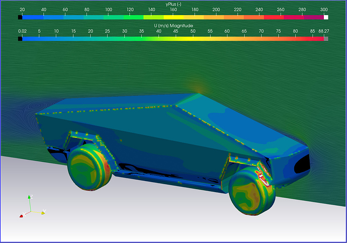
Here is a simple example of what ParaView can do which SimScale PP can not…

Note the surface LIC lines on the velocity plot slice and the detailed scaling control that is possible in ParaView (including Black/grey/white areas that show data areas above and below the scale limits :wink: ):

This y+ mapping was the work of someone else wrt layering and I just made this revealing y+ map for it…

Yes, in SimScale you will input them in meters (divide by 1000). But your table should be updated and if your domain is 10 metres wide, you would not use first layer of 0.45 m, but, for instance 0.00045 m.

Although I have seen SimScale have many problems when using English vs SI units, I have NEVER seen SimScale ask for meters when it wants mm… In fact, I have I have NEVER seen it ask for mm…

I do however THINK, in my head, of BL dimensions in mm because it is much easier to relate the actual BL dimensions in my wacky brain, in mm (not something like 6.5e-4m) :wink: , then when I put my brain mm’s into SimScale I divide by 1000 (which I can still do easily in my head :wink: )

EDIT: And a final word on the tutorial and your Post 1 issues —

  1. The value of ‘1st layer thickness’ which you should enter into your current project SimScale parameters for BL generation, is 0.00133m (if your mesh algorithm needs a 1st layer thickness in meters and if you entered the correct parameters and type of viscosity into the y+ calculator). The cfd-online calculator result is a ‘center of cell’ distance. 1st layer thickness = 2 times cell center distance:wink: If your mesh algorithm needs a different parameter, then set up a spreadsheet expansion table that uses 0.00133m as 1st cell thickness and calculate the parameter you need from that table…

  2. All of the tutorial ‘apparent’ discrepancies, should disappear if you can establish that ‘Layer size’ (it is on by DEFAULT by the way) was turned ON when that screen capture of its ‘Mesh Refinements’ was generated…
    I think the appearance of the (-) in your image, instead of (m) as units for ‘Thickness for final layer’ confirms my theory and tells me that it is indeed a tutorial from a previous version of the SimScale UI that at least changed the (m) to (-) when Layer Size was ON, even though the current SimScale UI shows (m) when Layer Size is ON, don’t even try to figure that one out :wink:

  3. Yes you should take the effort to properly set up your boundary layer cells.

Hopefully, you can mark this post as the answer to your topics 1st post, so people can easily come directly to here without the need to read all my other jibber jabber :wink:

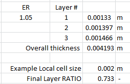
EDIT: And for the specific case of the BL in your 1st post, here is an expansion table that shows, for the current SimScale UI for HEXpara BL addition, that the parameter for ‘Final thickness (m)’ (it is really a RATIO if Layer Size is ON) = 0.733… (if your local cell size is 2mm :wink: )
image

Please do continue, even though you may have answers for the specific 3 issues which you had in your 1st post, as we have digressed quite a bit already…

Besides, your topic title suggests that there is to be more than the issues you asked about in your 1st post :wink:

Retsam

I used 0.45 (which i guess would be meters) for the final layer thickness because this is what the tutorial provided. This is why i asked the question about what this value should be because it seemed incredibly large, especially in comparison to the calculated Y+ values i was getting.

I think what Dale said about this setting (when the layer size toggle is turned on) makes the most sense, that the thickness of the final layer value is not actually the cell size thickness but the ratio between the final cell size and the neighboring cells. In this case 0.45 makes sense because that would mean that it would be about half the size of the neighboring cell.

I will be running another mesh with the layer sizing turned off, with the same settings. Based on this information, i assume that the mesh will either

  • fail with these settings

  • no layers will be created
    or,

  • i will get a crazy large boundary layer.

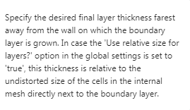
My money is on number 2. However having a definite answer that this is how the setting operates would be useful. The current description when hovering over the final layer thickness is as follows:
image

I find this a bit confusing but i guess it does make sense.

Thanks for your help!

Dan

image

With ‘Layer Size’ turned OFF you would need to enter 0.001466m for the ‘Final thickness’ parameter, else you will for sure not see much of what you seek :wink:

Wow thats a lot to take in, but extremely useful. I re-read your posts like 3 times to make sure i understand everything haha.

Part 1. What i meant with the “useless” comment was that with layer size on, the values you give dont really do what you want. Number of layers, and expansion ratio both work, but the final thickness, the most important value to determine the size of cells measuring Y+ is based on the surrounding cell size.

I dont want to keep explaining the same thing just in a different was. I think what you said is correct.

  • Layer size toggle on - (relative) = final layer thickness is actually the ratio between the final cell size and the neighboring cells.

In my case, 0.45 makes sense because that would mean that the final cell thickness would be about half the size of the neighboring cell.

  • Layer size toggle off - (absolute) = final layer thickness is exactly what it says. The final layer cell size.

However, in Layer size toggle off or (absolute) mode the ratio between the neighboring cells is not preserved, and could be problematic when different surface refinement levels or region refinement levels are used.

Ok i think that is now clear to me how it works and what i need to do to achieve what i am looking for.

I wasnt planning on taking that mesh through to simulation, but you called me out so now i have too :sweat_smile:

this is also a very cool observation that i missed. Y+ values would definitely need to change when interacting with geometry that causes velocity increases or decreases. However i think this would be absolutely bonkers to even attempt to do.

And yes i will be continuing to the other topics as my intention for this post was to have “total coverage” of this problem as well as optimizing the mesh so that accurate results can be achieved in the simulations - validation is key.

I really appreciate you sticking with me on this and “showing me the way” haha:sunglasses:

Empty post to separate topics
.
.
.
.
.
.
.
.
.

But with the method I specified, they WILL do what you want on the surfaces that are surface refined to that EqualMaxMin level which I mentioned (and those surfaces make up most of the surface area of where your want BL’s to be added)…

Don’t forget that your are in control here with relative layering, your neighboring cells size on the majority of the surface area which you are trying to add BL’s to, is determined AFTER you create your layer expansion table where you have decided # layers and ER to use…

Only then, do you decide on refinement level of surface cells in that majority area… I find that a final thickness RATIO is best in the 0.4 range (this goes for absolute layering too) … At this point you can tweek your Level0 cell size so that a suitable refinement level number gives you about a 0.4 ratio near the final layer…