Hi everyone
I will be documenting and experimenting on how to get the optimal mesh quality for an FSAE half simulation (and eventually full car) with focus on important parameters such as:
- Total mesh cell count - (dont want too many core hours / memory failure with 32 processors)
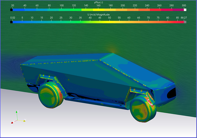
- Y+ Layer formation - measuring in log-law region 30<Y+<300 with first layer thickness = 30
- Illegal Cell count - The lower the better but not at the expense of omitting layers
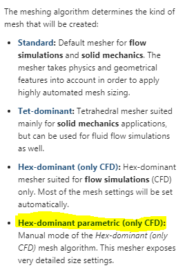
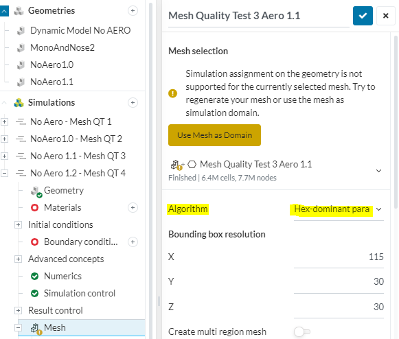
- Overall mesh quality and accuracy - Optimization of mesh controls (Castellated mesh, Snap, Layer adding, mesh quality)
I hope that some of the power users - at least the ones i know - can help me with this thread as I am surely not alone in having little knowledge in how to manipulate the controls and settings to get the mesh i am looking for.
@jousefm @Get_Barried @DaleKramer @Edoardo @Kai_himself @Retsam
- The first topic (more like question ) i would like to cover is for the optimal Y+ layer creation.
I have read through the documentation provided by Simscale for hex-parametric controls. and Y+ a few times over already and have also researched and determined that measuring the boundary layer in the log-law region is appropriate for an FSAE simulation.
My goal for this first topic is to optimize the first cell layer thickness so that it is ar the necessary Y+ = 30 throughout all surfaces in the model. This will ensure that the viscous sub layer region is being accurately “averaged”.
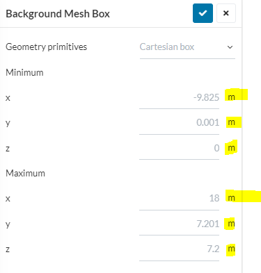
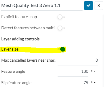
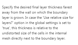
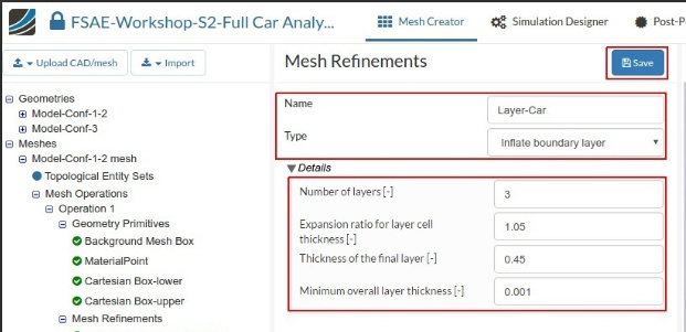
Using the inflate boundary layer settings provided by the FSAE Step-by-Step Tutorial: Homework of Session 2
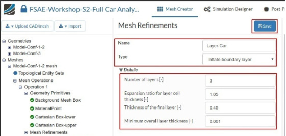
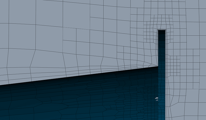
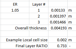
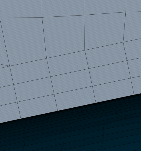
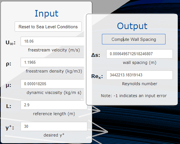
I created an boundary layer mesh shown below. While I understand that having an expansion ration of only 1.05 will result in a low difference in size between all three cells, a calculation of the first layer thickness (shown in second pic) results in thickness that does not seem right.
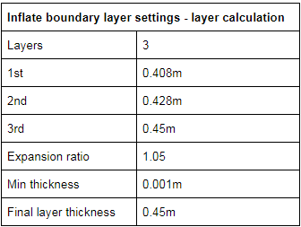
This is where I start to get confused because after reading about Y+ I learned that the first layer size can be calculated based on the desired Y+ distance. In this case I wanted 30. I had found 2 different calculators yet the results from each are different with the same inputs.
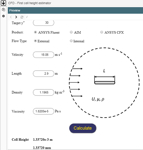
First Y+ Calculator Tips & Tricks: Estimating the First Cell Height for correct Y+ | Computational Fluid Dynamics (CFD) Blog – LEAP Australia & New Zealand
Using this calculator the estimated first cell size is 1.33720e-3m or 0.00137m
Second Y+ Calculator CFD Online - Y-Plus Wall Distance Estimation
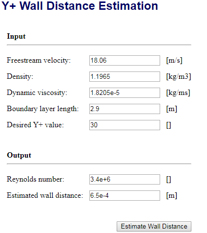
Using this calculator the estimated first cell size is 6.5e-4m or 0.00065m
These are two very different results, and to make it worse they are both very different from the suggested first layer thickness provided in the FSAE tutorial.
Calculator 1 = 0.00137m
Calculator 2 = 0.00065m
Tutorial = 0.408m
However, upon seeing the good layer formation of the bounding box layer addition settings (which is pretty much an inflated boundary layer but for the moving floor), these settings were used for the car boundary layer.
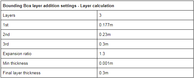
Which resulted in cells forming as shown below
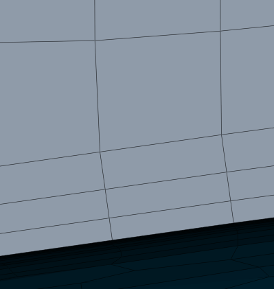
These settings result in a first layer thickness that is smaller but still not near to the Y+ of 30 of both calculators.
Calculator 1 = 0.00137m
Calculator 2 = 0.00065m
New boundary layer settings = 0.177m
Can anyone explain or verify the following questions
- What should the first layer thickness be for a Y+ of 30 in my situation?
- Are any of my calculator inputs incorrect which leads me to believe that the tutorial first layer size of 0.408m is too large compared to the calculators?
- Do you recommend investing so much effort into a correct Y+ cell size or is this goal unimportant for simulation accuracy in an FSAE car?
Many thanks to anyone with help or input. I will be adding post in the future to address the other goals of this thread. Thanks!
Dan

 )…
)…