RW Test 1.9
Changes:
- Suggested to change the bounding box to 1m
| Level 0 (calculated) |
1m |
| Level 1 |
0.5m |
| Level 2 |
0.25m |
| Level 3 |
0.125m |
| Level 4 |
0.0625m |
| Level 5 |
0.03125m |
| Level 6 |
0.015625m |
| Level 7 |
0.0078125m |
| Level 8 |
0.00390625m |
| Level 9 |
0.001953125m |
| Level 10 |
0.0009765625m |
| Level 11 |
0.0004828125m |
| Level 12 |
0.000244140625m |
- New boundary layer calculation to increase average Y+ values
0.001953m * X = 0.00182182m
0.00182182m /0.001953m = X
X = 0.932
| Inflate boundary layer settings - layer calculation |
|
Y+ Value |
| Layers |
3 |
|
| 1st |
0.001078 |
Y+ = 50 |
| 2nd |
0.0014014 |
|
| 3rd |
0.00182182 |
|
| Overall thickness |
0.00430122 |
Y+ = 200 = 0.004311 |
| Expansion ratio |
1.3 |
|
| Min thickness |
0.001m |
|
| Final layer thickness (RATIO) |
0.932 |
|
| Relative |
0.932 |
|
| Absolute |
0.00182182 |
|
- Region refinements added as distance from geometry in addition to wake boxes
- Trailing edges surface refinement level reduced
- Wing surface refinement level reduced
Results:
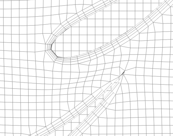
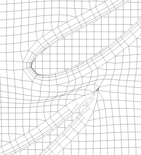
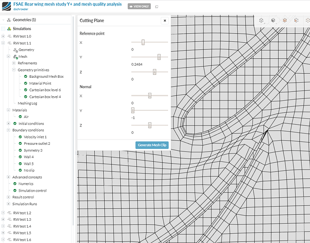
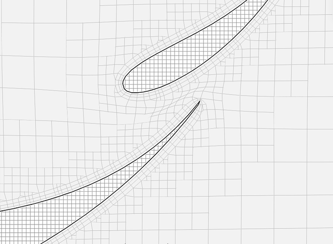
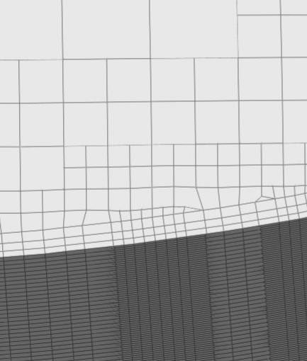
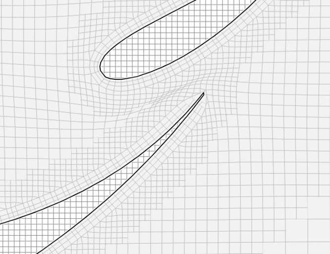
Test 1.9 Pic 1: Cell squish between main wing and elements. Not many cells shown of level 9 region refinement at 0.001 - must increase distance from geometry.
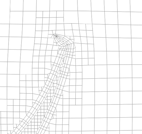
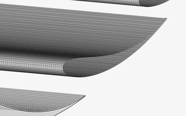
Test 1.9 Pic 2: Cells are not even along wing surface - solutions could be adding feature refinement or unequal min max of refinement
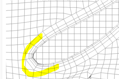
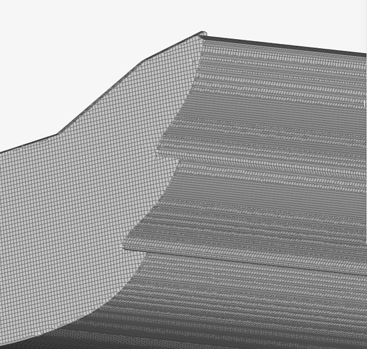
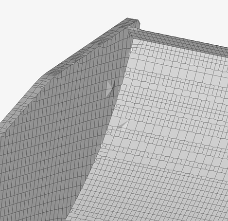
Test 1.9 Pic 3: Shown again the surface refinement levels of the wing surface affect the boundary layer cells making unequal cell sizes - no bueno
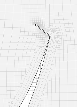
Test 1.9 Pic 4: Trailing edge gurney flap boundary layer is well meshed
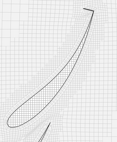
Test 1.9 Pic 5: Trailing edge of 1st element has jagged trailing edge
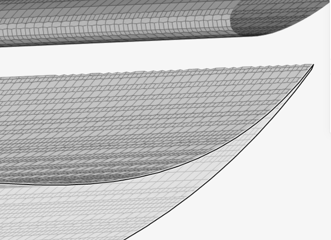
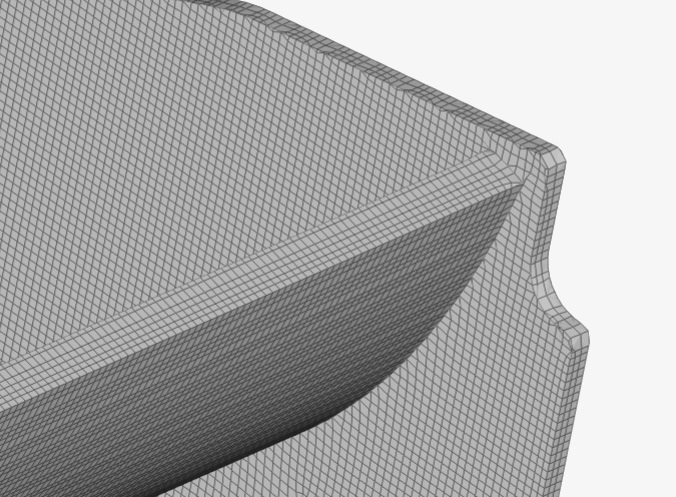
Test 1.9 Pic 6: Edge of endplate has some odd cells - solution could be unequal min max levels
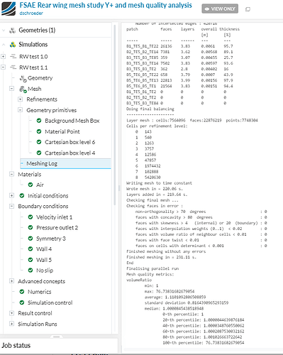
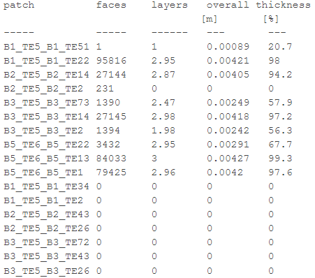
Test 1.9 Pic 7: Layering chart from the meshing log. Thicknesses are good in some areas but need to be approved in others.
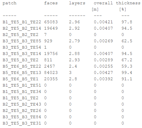
Overall results: Surface and region refinements need work
RW Test 2.0
Changes:
- Exact same as test 1.9 but with feature refinement
- 0.0004 level 11
- 0.0009 level 10
Results:
Test 2.0 Pic 1: Region refinement level 9 is more prevalent even though the distance is not changed. Trailing edge boundary layer cells gone in main wing trailing edge. Squish is reduced slightly
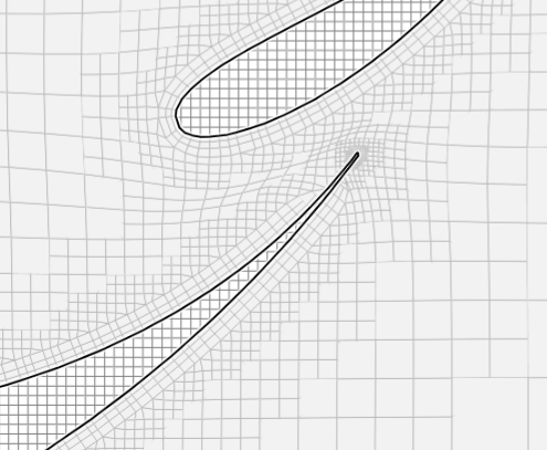
Test 2.0 Pic 2: Gurney flap boundary layers gone, but cell refines to a lower level - most likely to surface refinements moving to lower levels
Test 2.0 Pic 3: Main wing trailing edge has many jaggies even though cell size is reduced near the edge
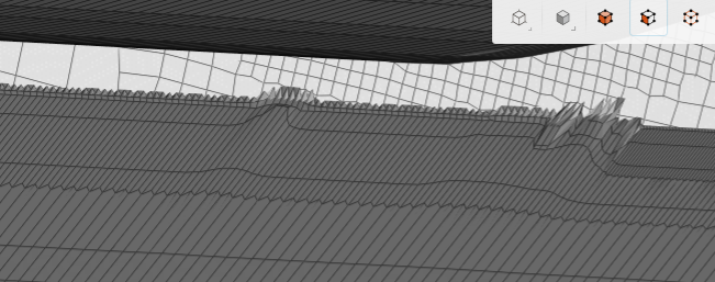
Test 2.0 Pic 4: Gurney flap has some bad cells
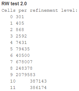
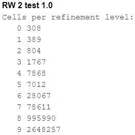
Test 2.0 Pic 5: mesh thickness log shows less coverage then test 1.9 without the feature refinement.
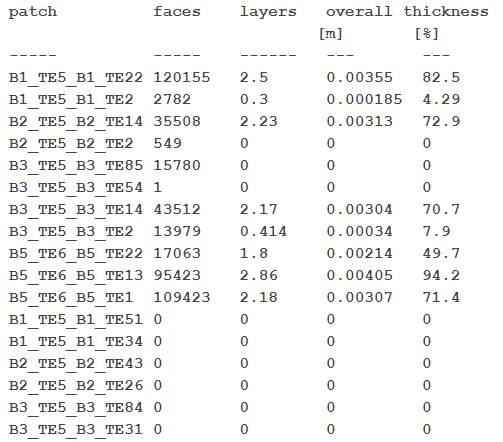
Overall results: Feature refinement allows transition to designated higher level surface refinements to show up. In test 1.9 the higher level trailing edge refinements (especially at the gurney flap) are not recognized
RW Test 2.1
Changes:
- Distances to surface of region refinement increased
- Feature refinement removed
- Wing surfaces surface refinement changed to min lvl 9 max lvl 10
- Endplate main surface refinement increased to lvl 8
- Wake region refinement levels reduced
- Wake region box smaller
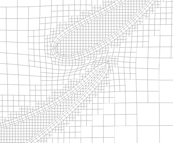
Test 2.1 Pic 1: Increased region refinement level 9 to 0.005 gave better results then test 1.9. Increased distance of level 9 did not help with cell squish - solution, maybe this needs to be increased further to conjoin the two regions
Test 2.1 Pic 2: Same as pic 1 Showing how the surface and region refinements are related. It can be seen that in Test 1.9 Pic 1 with a region refinement distance of level 9 at 0.001m away from the geometry, this does not surpass the overall thickness of all three layers which results in 0.0043m This is why the level 9 region refinement doesn’t show up well on the mesh clip and seems to go directly to the next lower level 8, which was set at 0.005m. In this picture below the level 9 region refinement distance was changed to 0.005, and level 8 to 0.01m which is why there is better coverage outside of the boundary layer. Understanding that with distance from geometry region refinements, the first level distance value should be larger then the overall thickness of the boundary layer.

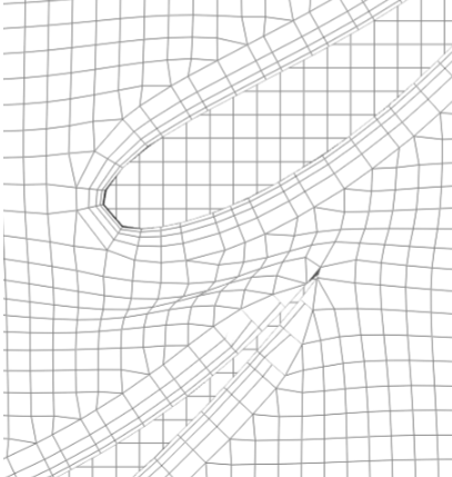
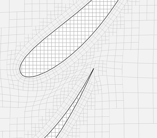
Test 2.1 Pic 3: Cell squish is still apparent even with increased level 9 region refinement distance.Also notice that the boundary layers near the trailing edge have disappeared. - solution could be to make unequal min max levels for trailing edges
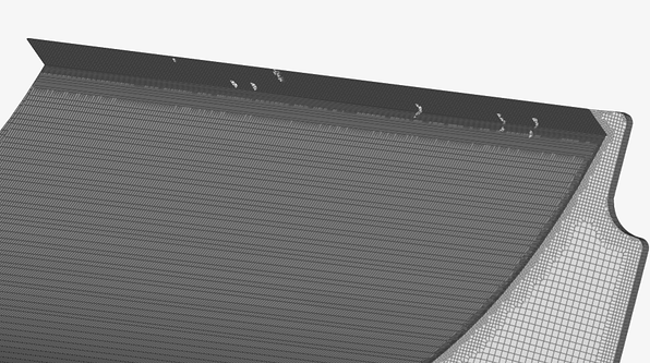
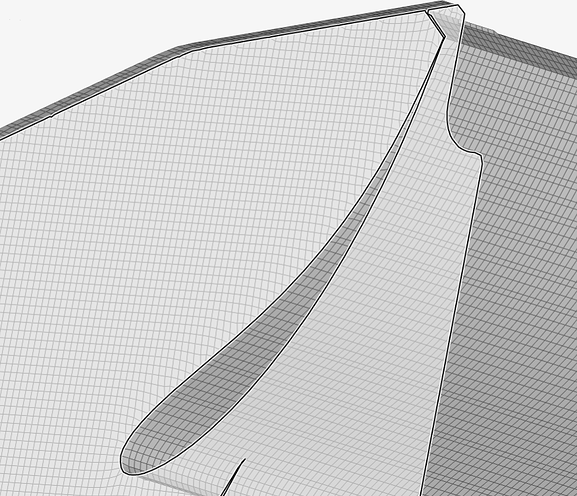
Test 2.1 Pic 4: Endplate edge cells are better and wing surface cells are also better.
Overall results:
Boundary layer depletion around trailing edge - no good
Cell squish is not gone - solution is to increase the distance of level 9 region refinement
RW Test 2.2
Changes
- Increased region refinement distance of highest level - level 9 = 0.01
- Increased trailing edge level to min 11 max 12
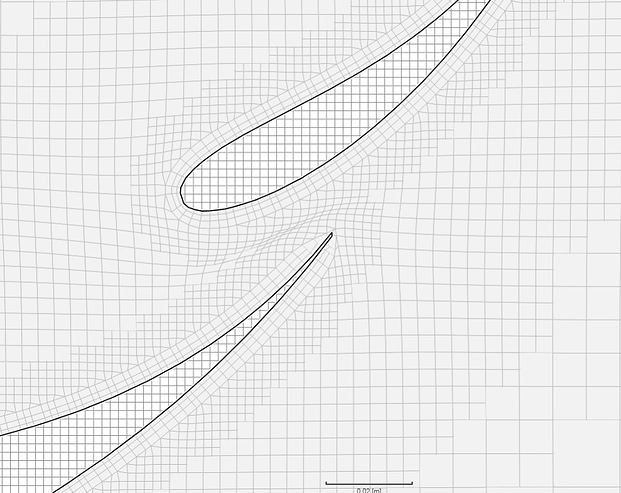
Test 2.2 Pic 1: Increased level 9 distance did not remove cell squish
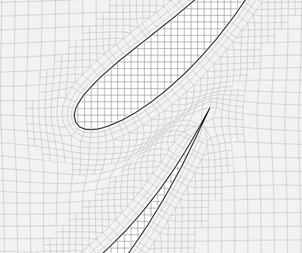
Test 2.2 Pic 2: Trailing edge boundary layers gone still between 1st and second element
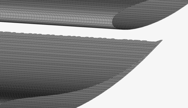
Test 2.2 Pic 3: Trailing edge has jaggies just like test 1.9. I think the unequal cell sizes on the surface refinement is to blame. Not sure how to fix this
Overall Results: Need to find new solutions to problems
