Hello,
CONTEXT
I am currently trying to optimize an axial flow multistage impeller of diameter 85mm for a waterjet engine model. What I am trying to optimize is the pitch of the rear impeller blades and the configuration of the front and back impeller (i.e if the vanes from the front impeller are in line/30/60/90 etc. degrees ‘out of step’ from the rear impeller)
I am trying to optimize this by calculating the efficiency and thrust of each configuration and trying to maximize both values as shown in the simscale youtube tutorial: “how to optimize a propeller/fan design”.
Project Link
NOTE: the hole in the mesh on the intake side is to simulate the interaction of the fluid with the drive shaft.
PROJECT SUPPORT
Issue 1
The motor I have available has the following specs:
Kv value: 330kv
Power: 2500w
Voltage: 11.1-36v
This theoretically means the maximum rpm would be 11880 which is completely unrealistic for turning an impeller in water so I was wondering if there was a way to accurately find the rpm the motor would turn if under the viscous drag of the impeller as I need to enter the rotational velocity prior to running the simulation. (I have used 600 rads-1 as a boundary condition which leads to issue 2)
Issue 2:
Furthermore, in the simulation I ran, the total force in the Z direction (at 600 rads-1) is shown to be around 110N from the post processing graph , however this seems way too high for a 2500W motor.
As P=T×ω
where T = F x r = 110N×0.0425m=4.675Nm
P = 4.675 x 600
= 2805W ==> this is more than what the motor can supply at 100% efficiency.
NOTE: it also appears this issue also does not come from a lack of detail in the mesh as I ran one simulation with 8 million cells and one with 16 million cells
MAIN PURPOSE OF POST:
I am wondering what boundary conditions/result controls/geometry of the simulation would I have to change to find the torque, thrust and hence calculate the efficiency via the advance, thrust, torque and power coefficient for an axial flow pump impeller in a casing to simulate a waterjet without an intake
Warm Regards,
Lasse
Hi @lasse_veith, thanks for posting on the forum and welcome to the SimScale Community 
I’ll take a look at your project shortly and provide an answer as soon as I have some feedback to produce.
Best,
Igor
Hi again @lasse_veith,
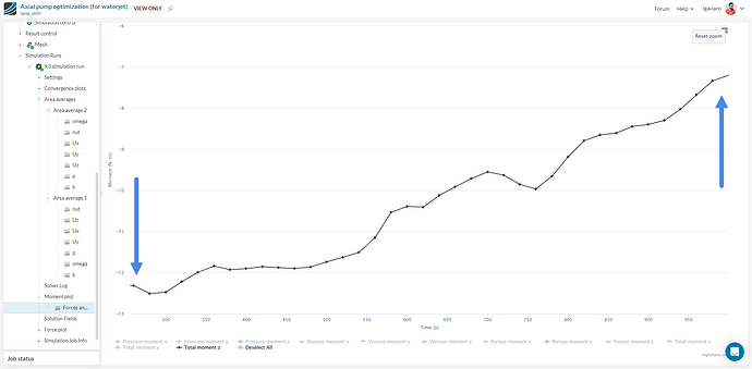
In my evaluation, you shouldn’t use the reaction force in the z direction to calculate the torque, since it should be produced by the tangential force using the radius of the impeller as a lever. However, there is another plot in the results called “moments plot” where you’re able to get the moment around the z axis (which is what you’re looking for). However, if you look at the graph produced for the total moment:
The solution shows signs of divergence.
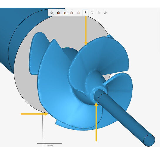
This is probably due to your mesh’s low quality, which in turn is caused by your CAD model having rough surfaces such as these ones:
On mesh quality and divergence, I advise you to take a look at the following resources:
As a sidenote: if your CAD contains these unwanted features, usually it doesn’t matter how much you refine the mesh (to a resonable degree), the resutant one will remain low in quality. The best approach is to import your geometry in formats such as STEP or Parasolid or apply cleanup operations in an external CAD tool. STL is usually to be avoided when it comes to CFD simulations (except for ones which use a cartesian mesh).
1 Like
Before attempting to predict power through CFD simulations, it’s important to first establish a relationship between impeller diameter, RPM, and absorbed power. This approach is more practical, especially if you’re not considering all possible factors in your simulations. Remember that cavitation is a limiting factor as well, and if the CFD solver you’re using doesn’t account for cavitation (which is typically limited to certain multiphase flow solvers), the results may be misleading. Thefore, try searching an empirical/experimental curve-relation showing this relation for typical impeller designs.
If you are confident that you are working within non-cavitating ranges, you can easily calculate the power drawn from the torque, as outlined above. By calculating the power at three different RPMs, you can then interpolate your power curve.
However, be aware that numerous factors could affect your calculations, such as turbulence, domain size, and grid resolution. These variables have the potential to significantly influence your results.
I hope this helps.
Jairo
1 Like
Hello,
Thank you very much for the support with the project. I greatly appreciate it.
Over the last few days I have been experimenting with the following software to try convert my mesh to a NURBS file (i.e STP/IGES). I have used rhino, onshape and freecad however I have not figured out how to create the STP file, or the one time I managed to import it into simscale it was a 150MB file and the meshing was canceled due to not having enough processors.
I have however refined the mesh and it looks much cleaner now, however I believe there is still divergence taking place on the moments plot.
Is there a way I can convert a mesh to a NURBS some other way (preferably free/trial).
In regard to the RPM at various torques from the motor I do not have access to equipment that allows me to measure the RPM of the motor at different torques experimentally , is there a way I can estimate the rotational velocity completely theoretically based off of the motor specs. (manufacturer did not supply any torque power graphs or similar)
Due to the pitch of the impeller (50 progressing to 20 degrees) I believe cavitation will most likely not have any major effect which deviates the simulation data from the real world.
TO CLARIFY: in terms of domain size, are you referring to expanding the flow region and to simulate the outlet flow in a larger non cylindrical cartesian cube? (in order to allow the flow field to develop more)
Regards and thanks for the feedback again,

