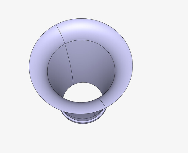
Here, I watch the tutorial with the pipe, but on their example, the pipe is first designed as a bar with faces on the extremeties. But on my cad, I don’t have any faces to put the velocity inlet and pressure out.
Hello @lidwyn , and thanks for using the Forum!
The geometry at the moment only includes the solid parts, hence first you need to create an internal flow volume operation in the CAD mode, and solid parts should be removed from the model. (If Incompressible or Compressible) Only then, inlet and outlet boundary conditions for a fluid analysis can be defined. Please find more information in this documentation page, and this supporting knowledge base article on how to select seed and boundary faces when creating internal flow volumes.
I hope these are helpful,
Best!
Thanks for your advices, it is very clear now. I’m gonna try to do what you told me in the CAD mode, and if I have an issue I’ll come back to you.
1 Like
