Hello,
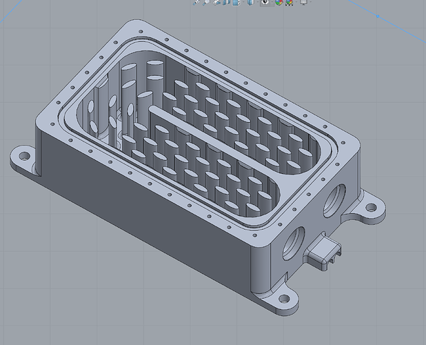
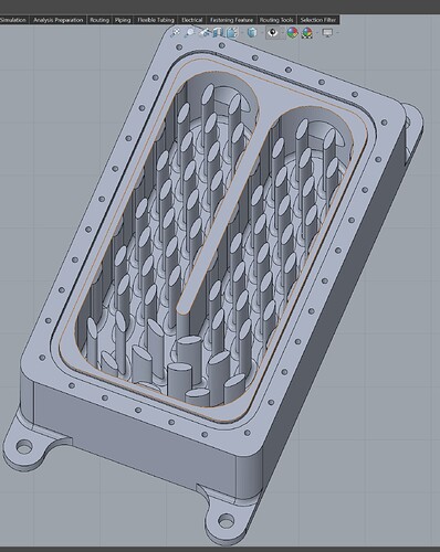
I’m making a fluid heat transfer block/water boiler block. The block goes onto heat source, water gets pumped into it, and aim is to heat up the water.
To increase the surface area there are lots of fins inside, and fluid needs to turn 180, so the fins at the turn are in a radial pattern.
I wanted to simulate the flow to see what it might do, and see if there are any massive dead spots.
My project is here
Or here
I used the “Tutorial: Fluid Flow Through a Non-Return Valve” to help with the set up. I didn’t follow it 100% but I managed to simulate it and got some data.
Some setup things I’m not sure are correct:
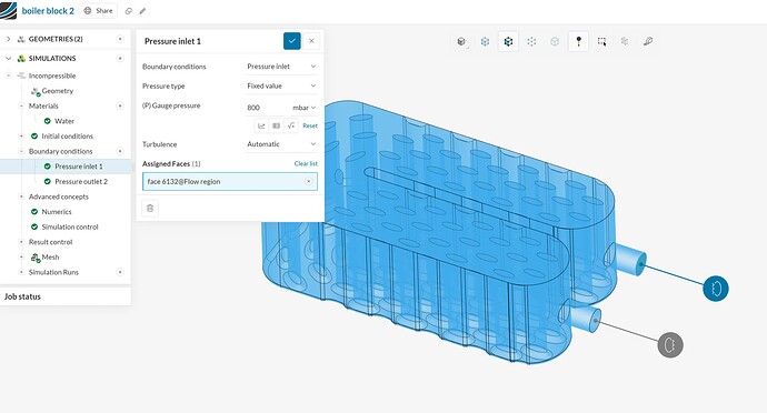
Pressure inlet 1: I set this to 800mbar, because that is the max pressure of the pump that will be supplying the water into the block. Not sure if that that was the correct way to set this?
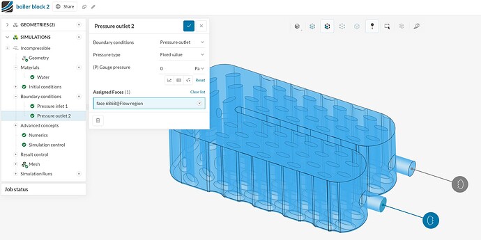
Pressure outlet 2: This was set to 0, but the unit was Pa. Does it matter that the inlet is set to mbar and outlet set to Pa?
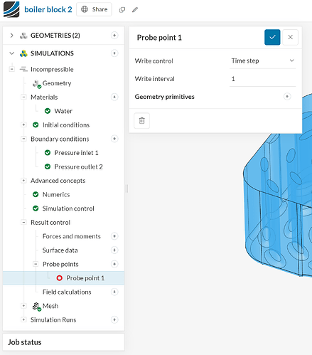
Probe point 1: Before running the sim I got a “Simulation setup has warnings” - There are settings defined in the simulation setup which have empty assignments and hence will be ignored for the simulation run. Names of the settings that will be ignored: Probe point 1
Is this a problem? I wasn’t sure how or where to set a Probe point. I read the guide but it wasn’t clear what to do in my situation.
Sim seem to run fine. I made some Cutting planes and Particle traces.
Problems and odd things I’m getting:
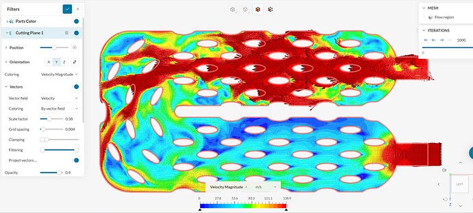
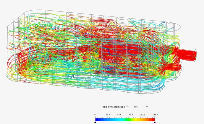
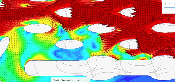
- I had to set the Cutting planes and Particle traces settings very fine to see anything, nothing like the example projects. My block is small, only 120mm x 74mm. Does the size of the model play a factor in the settings? (see image bellow)
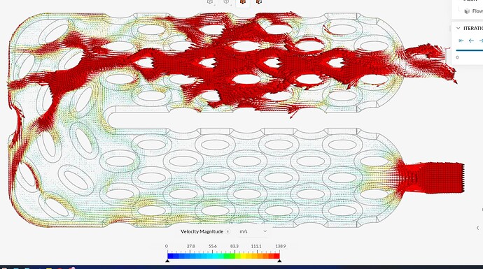
- With the cutting plane I struggled to get the vectors visible, the ones at the higher magnitude seem to become very big quickly, and the lower ones are very small. Have I done something wrong? or is normal?
- I can’t make it look as nice as all the example I’ve seen. Am I doing something wrong? Or do I just need to use it more and try different settings? (see image bellow)
Interpreting results.
-
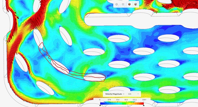
If I understand it correctly, water comes in good, good flow over the middle fins, but then at the end when it turns, start to go bad. In the middle at turn, the vectors show the flow going the opposite way?
-
This was interesting, I don’t understand what happening?
-
I think making this one piece could help?
-
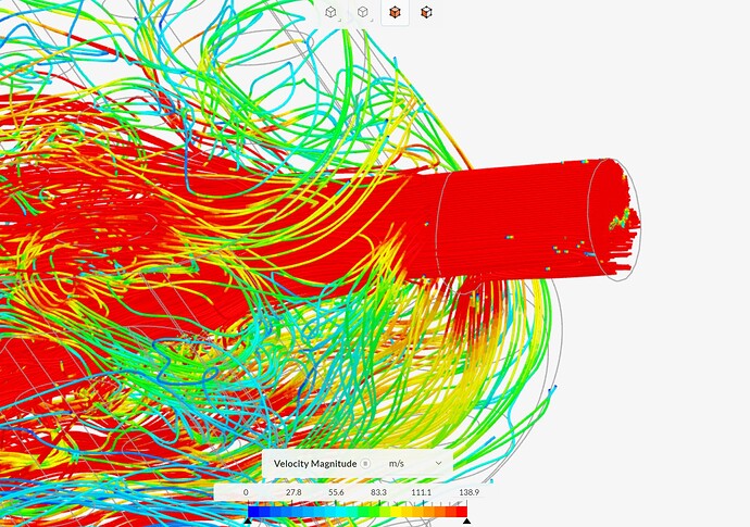
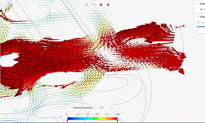
This was interesting, it’s on the inlet, The Particle traces show, I’m assuming lots of flow, but the Cutting plane vectors show a lot of flow going backwards? and I don’t know what to make of that?
This is the 1st time I’ve use SimScale, I just want to know if these results are semi correct before I start making changes?
Thank you
