Hello,
I apologize in advance for the very long post
I am currently creating a study where I would like to predict the efficiency of an APC 11 x 5.5 propeller at constant RPM as the advance ratio increases. I then want to compare SimScale’s predictions with the measured UIUC data. My methodology is explained below:
I saw that SimScale already has a sample validation case with this specific propeller (Drone Propeller Study | Validation Case | SimScale), though this test is for static conditions only. Regardless, I used this exact project link as a starting point and copied it to my workspace.
I made the following changes from the settings that were originally in place for the static tests:
-
Changed “Non Orthogonal Correctors” from 0 to 2 since the max Non-Orthogonality is 83.015 according to the meshing log (I am also surprised at the fact that the Non Orthogonal Correctors were set to 0 and not 2 in the SimScale static tests).
-
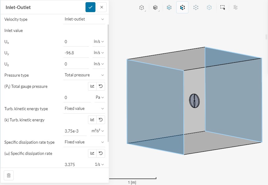
Changed the inlet/outlet boundary conditions to “Velocity Inlet” (set in in/s calculated from advance ratio) and “Pressure Outlet” (0 gauge pressure)
-
Changed the “Materials - Air” assignment to be assigned to just the flow volume (Part 2), it was previously assigned to both the MRF (part 1) and the flow volume (part 2). SimScale would not let me start the simulation when I first tried, and gave me this error: “In single region simulations, only the fluid region can be assigned to a material. Please review your material assignments, making sure that only the flow volume region is assigned.”
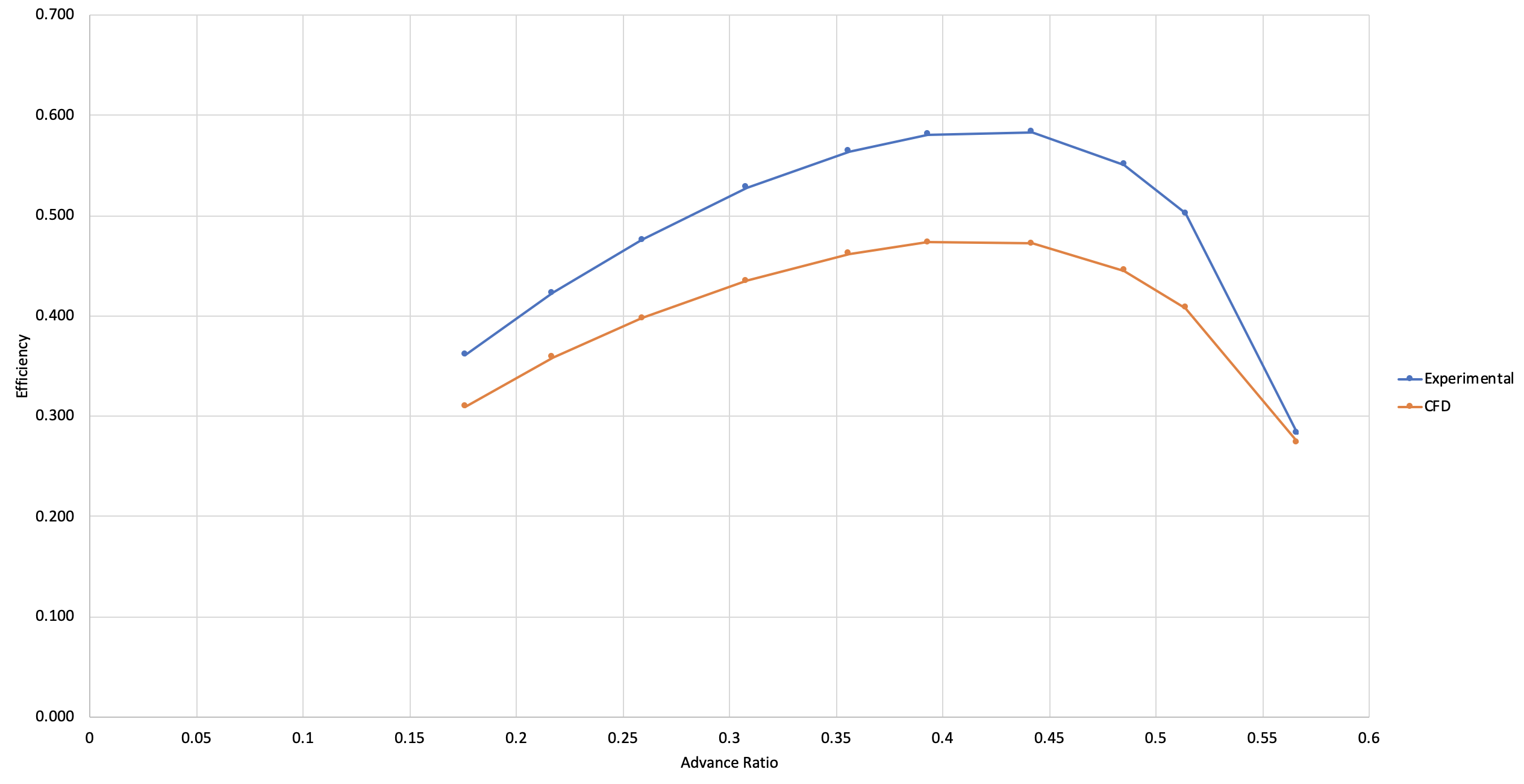
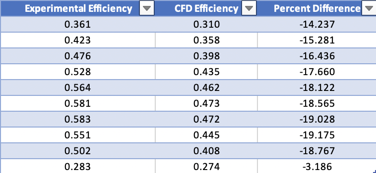
For all simulations I used “Mesh 3” which had y+ values of < 1 (according to the post processor) for the full resolution boundary conditions along with 3000 RPM (I initially did 6000 but it was no longer incompressible after checking the velocity magnitudes so only at simulation runs with “3000 RPM” in the title, the rest are 6000 RPM). After running several simulations at advance ratios that were listed by UIUC, and computing the efficiencies from the “Pressure Force Y” and “Pressure Moment Y” values. I came up with the attached graph and table.
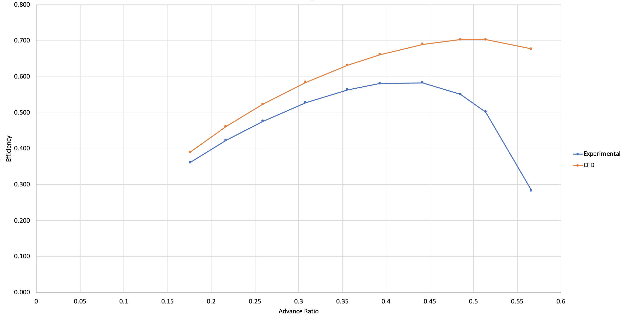
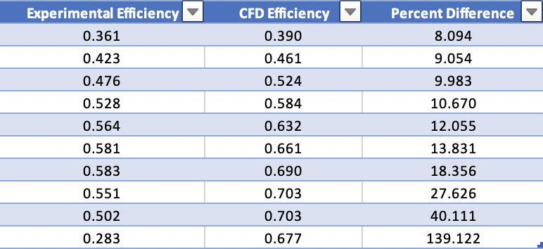
I was quite surprised to see that the predicted efficiencies were very different from the UIUC data, especially since the static test data computed by SimScale in their validation case matched the UIUC data quite nicely. I was expecting to get values closer to the UIUC data, seeing as I was using the same propeller CAD model with the same refinements. This leaves me with the following immediate questions which I believe will help me solve my issue:
-
Why am I unable to start a simulation with air assigned to both the flow volume and MRF zone when it was done by SimScale already in their validation project (in Jan 2021 according to the simulation runs)
-
What effect would this have on the numerical accuracy of the simulation if any
-
Am I correct in saying that the y+ values for my simulations are good for the full resolution boundary condition given the fact that they are below 1?
-
Could the velocity inlet and pressure outlet boundary conditions be the culprits? Do I have to create velocity inlet and pressure outlet conditions where I specify turbulent kinetic energy and specific dissipation rate values?
-
Is there anything else I may be overlooking when setting up the simulation? The results all seem to converge.
PROJECT LINK: https://www.simscale.com/workbench/?pid=6220943220511267184&mi=run%3A103%2Csimulation%3A7&mt=SIMULATION_RUN
UIUC 3000 RPM Data: https://m-selig.ae.illinois.edu/props/volume-1/data/apce_11x5.5_kt0516_3010.txt
FINAL NOTE, I do not believe (or hope) that my calculations are wrong but I used the following:
Density: 1.196 kg/m3
n = 50 rev/s (3000 RPM / 60s)
D = 11 in (or 0.2794m since forces and moments are in N and N-m)
CT = Thrust / (Density * n^2 * D^4)
CQ = Torque / (Density * n^2 * D^5)
CP = 2 * pi * CQ
Efficiency = (CT/CP) * Advance Ratio
Thank you very much for your help and I apologize for such a long post but I wanted to explain my issue as clearly as I could.