I’m working on a turbine project but I can’t seem to understand the settings for the hex-dominant parametric meshing. Previously, I used Flow3D software, where I could input the cell sizes directly for my meshes and it would automatically compute the number of cells. I created 2 mesh blocks there: a big one for overall flow domain and a small one surrounding the turbine.
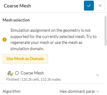
However, I decided to move my project to SimScale due to hardware problems. The thing is, I want to recreate the same mesh blocks just like in Flow3D but this error pops up.
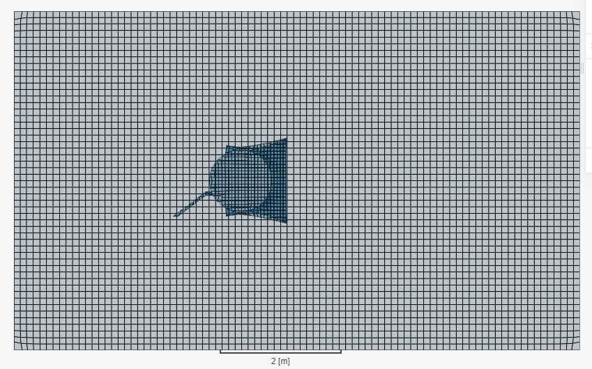
What I did was based on my desired cell size (0.05 m), I input the number of cells in the bounding box resolution. Then, I edit the size of the background mesh in geometry primitives to the size of my external flow domain. I created a cartesian box surrounding my turbine and applied region refinement of level 1 . I left everything else at default settings. It did generate the mesh like this.
But, I don’t know how I should properly refine it and this error pop up is confusing me whether my meshing failed or not. Because in Flow3D, I refined strictly by cell sizes of my bigger and smaller mesh blocks only, I’m not sure if this is also possible in SimScale as it seems like I need to refine other things.
It’s a private project so do let me know if you want to see the project, I’ll share with you.
If anyone can point out about the necessary settings I might have overlooked, I’d appreciate it very much. Thank you!
Hi @nuofei thanks for posting on the forum and welcome to the SimScale Community
At first, I’d advise you to take a look at this tutorial where you’ll find valuable tips and workflows to generate a Hex Dominant Parametric mesh with the desired parameters:
To run a simulation, you’d need to click the option “use Mesh as domain”, since the boundary conditions will be applied directly on the mesh for the Hex Dominant Parametric option.
If you need further advise, please share your project’s URL for us to take a closer look!
I think, I get what you mean now. I got confused because some tutorials show that we need to create the external flow domain plus cylinder for rotating zone in CAD mode. Then, to delete the bodies of our geometry. So, I followed that CAD preparation step.
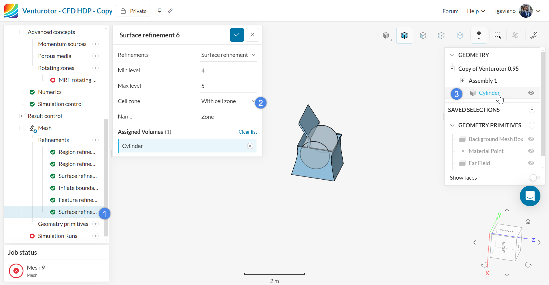
Does this mean for hex-dominant parametric, the background mesh box will already become our external flow domain? How about the cylinder for MRF? Do I still need to prepare it in CAD mode or can I just create it under mesh refinement with geometry primitives? If I prepare the cylinder in CAD mode, do I need to delete the bodies of my turbine geometry or just leave it be?
Thank you @igaviano for replying to my problem. Anyway, just a suggestion, maybe SimScale team can create a video comparing methods for geometry preparation for standard mesh and hex-dominant mesh. Because beginners like me can get easily confused on this part. Or maybe update in the tutorial for hex-dominant parametric mesh of front wing that we “don’t need to prepare external flow domain or cylinder for MRF in CAD mode like in Standard Meshing” . Something like that.
Hi @igaviano . I tried generating my mesh after setting the mesh as my domain. But, it’s taking too long and there’s an error that popped up. Here’s the link to my project. It’s the mesh labelled as HDP 1.
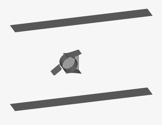
I tried running another mesh, HDP Test. It completed but it didn’t mesh the entire domain. Just the top and bottom faces of my domain plus the turbine. Why is it like that?
Unfortunately in the case of the Hex-Dominant parametric mesh, the cylinder for the rotating zone will have to be created after the mesh’s generation, to my knowledge.
I’ll run some tests and let you know of my findings later on