Dear SimScalers,
in this weeks spotlight we will have a look at a FEA simulation of a Gantry Crane by our PowerUser and partner @BenLewis that was used to demonstrate the process of defeaturing a geometry for a faster and easier simulation.
Check out our partner: Simulation Software | Engineering AI in the Cloud | SimScale
Introduction
This project was created to demonstrate various techniques used to simplify geometry for simulation. It is also useful to demonstrate the use of elastic elements to stabilize members where “physical contacts” are used.
The webinar is mainly talking about six steps:
-
Preperation of the geometry
-
Stages of Geometry Preperation
-
Geometry simplifications using SolidWorks
-
Simulation with SimScale
-
Live demonstration on our platform
-
Demonstration of the results
Geometry
Format: STEP
The original crane geometry was created by GrabCAD member coadong and can be found here
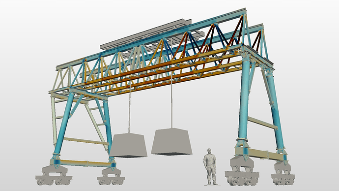
The man standing in the image below (for scale reference) was created by GrabCAD member minhkhoi and can be found here.
The image below shows the original geometry on the left and the simplified geometry on the right. The original geometry has 2656 solid bodies. The simplified geometry has 60 solid bodies (12 structural members, 16 pins, 32 elastic stabilizing elements).
Meshing
Type: Tet-Dominant Mesh
Mesh nodes: 1,385,884
Mesh elements: 7,304,361
Contact slave nodes: 19,091
Simulation:
Type: Static Analysis - Advanced
Simulations Details
Solution
Machine cores: 32
Run time [min]: 152
Core hours: 81
Memory [GB]: 42.8
Numerics
Equation solver: MUMPS
Results & Conclusion:
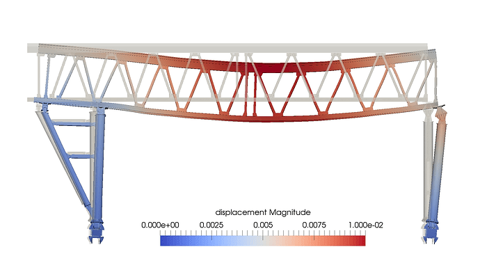
Results - Deflection
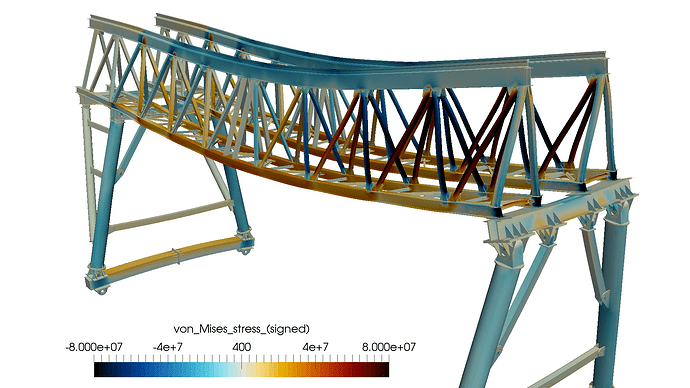
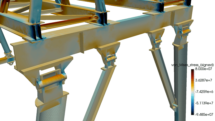
Results - Von Mises Stress (Signed)
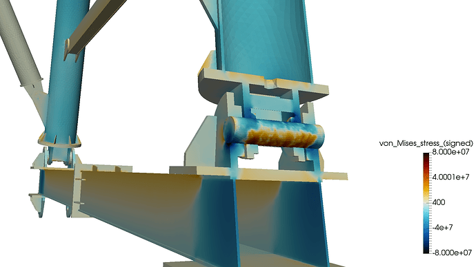
Results - Pin Joints
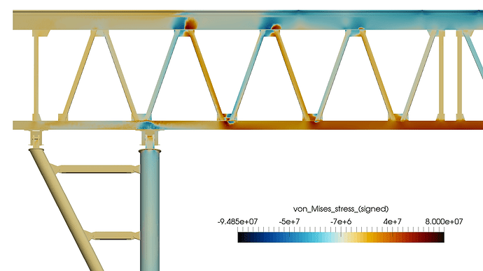
Results - Girder Stress
SimScale project:
To look at the simulation setup, please have a look at the project from @BenLewis :
Gantry Crane - Custom Machines [!!!THIS LINK IS NO LONGER AVAILABLE!!!]
To copy this project into your workspace, simply follow the instruction given in the picture below.


