Description:
Overview
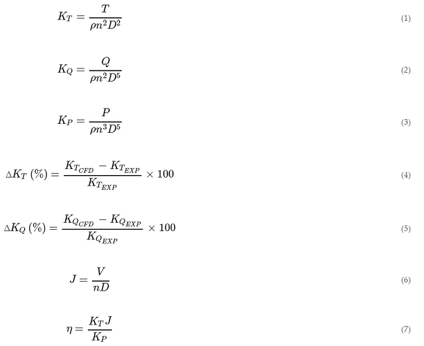
Propellers form an integral part in thrust or lift in fixed winged aircraft as well as in multi-rotor drones. Hence, it is crucial to model the performance of the propeller in the design process. This is where simulation tools can be leveraged. Computational Fluid Dynamics helps quantify the lift and drag values which form the basis for the calculation of parameters such as:
From [1]
Here, T (N) is thrust, Q (N·m) is torque, n (rps) is the rotational speed of the propeller, D (m) is the diameter of the propeller, and ρ (kg·m−3) is the density of the fluid. The relative percentage error of the thrust coefficient, KT, and torque coefficient, KQ, can be calculated by the Equations (4) and (5).
Input Data
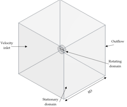
The proceeding figure provides an overview of the simulation setup for your simulation.

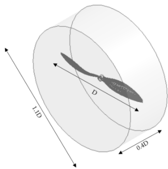
This project provides a good opportunity implement the Mixing Reference Frame (MRF) method. A detailed description about sizing the MRF zone can be obtained from the following image.

- The geometry for the APC slow flyer can be downloaded from here.
- The experimental results can be found on the UIUC Propeller Database. Please use the Slow Flyer 8 x 3.8 for the purpose of this validation case.
Purpose
This project is intended towards validating the performance of a generic propeller geometry. Such a validation project enables the user to enhance their knowledge in leveraging CFD for modelling the performance of an existing drone or estimating the design parameters such as motor size, material property requirements, etc. during the development phase of a drone.
The user has the opportunity of assimilating and applying CFD best practices at different phases(CAD clean-up, meshing, simulation and post-processing) of the CFD process. Some such best practices include: a mesh independence study, result verification, reasonable selection of time-step size and the number of computing cores. The would be provided with significant bonus points for implementing a automation (via shell-scripts for example) at any stage of the CFD process.
Key Words
Validation, Rotor Performance, UIUC Propeller Database, Aerospace, Drones, OpenFOAM, Slow Flyer,
Literature & Sources
- [1] Aerospace | Free Full-Text | 3D CFD Simulation and Experimental Validation of Small APC Slow Flyer Propeller Blade
- [2] UIUC PDB - Vol 1
- [3] Geometry source: https://grabcad.com/library/apc-8-x-3-dot-8-slow-flyer-prop/files
