I am attempting to set up some stress tests for my car parts but i’m unsure which boundary conditions and contacts to apply.
The tether line guide should be able to support a 200g weight as well.
Hey there revolateracing,
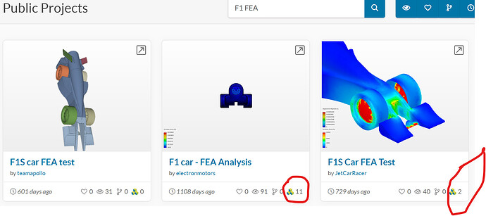
I had a quick look at your geometry and then did a search on Public Projects using the search terms ’ F1 FEA ’ several projects came up and hence I suggest looking at these projects that are similar to your one. Also on the tile of the project at the bottom right corner there is a symbol showing how many simulations have been done. Sometimes failed simulations are also counted and those that are deleted may be counted, but regardless it indicates someone has been doing some simulations and possibly work a look. Its worth looking at their boundary conditions and setup for FEA.
Search bar located in top right hand corner of you Dashboard page, will allow you to search for similar projects.
Here is the symbol that tells you how many simulations on a project…
Whilst the FEA tutorials might not be exactly what you are after they do provide knowledge and worth reading to get a feel for FEA simulations. SimScale Tutorials and User Guides | Cloud-Based CAE | SimScale
I look forward to your FEA simulations.
Kind regards
Ted
Hi Ted, thanks for replying.
We did some more research and created a couple simulations. Would it be possible for you/anyone else seeing this to take a look at them and see if we’re doing it the right way?
Hi Revolateracing,
Sorry this got a bit long, hope it helps you on your engineering careers.
Happy to help where I can, but I haven’t exactly done the simulations you are doing. My simulations have been confined to aerodynamic cfd incompressible flow simulations of propellers. Ok, but I’m a civil engineer, so I’ll make some overall engineering comments. So a learning opportunity for me as well.
This tether line guide image was originally set to display the Von Mises Stress is it correct? I don’t really initially know, so this is the process I go through & I politely suggest you do the same, as you can answer your originally question ‘if we are doing it the right way?’ If the results appear reasonable and some hand calculation checking key areas are ok, then you can reasonably assume that the Simscale model setup and configuration are working correctly.
A quick answer to reassure you…Your simulations seem reasonable based on your assumptions, but there are some minor areas for improvements, so please read on you may wish to make some small adjustments to you models like removing the atmospheric pressure as this appears to provide no benefit, unless I’m missing something.
When I consider similar engineering matters, I look at the configuration of the model, does it replicate the actual real world situation, are my loads, supports correct, are the simplifications and assumptions valid for the assumed homogenous model simulation materials etc (ie 3d layer printing produces non-homogenous materials). I usually look at the stress once I have confirmed the deflections appear ok. Do the results of the stresses make sense given the forces, imposed loads and supports? The easiest way, is to look at deflections and the image below shows the vertical Z deflections, which are very small, but you object is relatively small, but seem ok, but the extent of your support conditions should be checked.
So assuming the model imposed forces, supports are reasonable assumptions, I then look at the simulation model outputs, starting with deflections, as these are intuitive to a degree.
- Confirm the model is deforming as I’d sort of expect (Are the supports not moving?)
- Direction of the deflections - ( Are they correct and moving as expected?)
- Relative magnitude of those deflections ( Deflection max under the max load?)
- Actual magnitude of the deflections (simple hand calc’s confirm deflection)
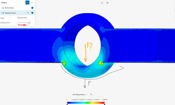
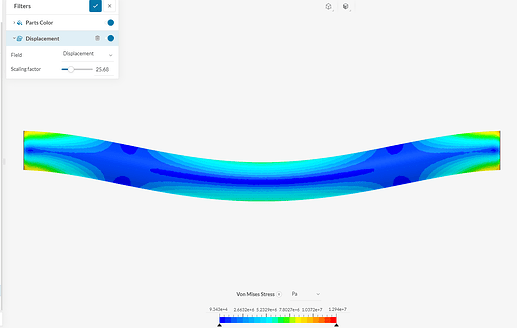
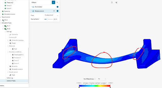
So all I did to check your model was slide the displacement scaling factor to the right (red arrow) and confirmed the deflections went in the expected direction and the magnitude seemed reasonable given the low loads and back-calculating the imposed model loads of -2N you are applying 200g. But the load should be applied inside the ring and concentrated in the bottom of the ring possibly by a point load, but your simplification of applying the load on the bottom outside of the ring would still possibly be ok, but you will not see an expected higher stress concentration at the bottom outer part of the ring. ie the coloured stress will be different. You are also assuming the the ring is supported right up to the sides of the ring, this is possibly incorrect and suggest you verify the extent of the actual support condition as I suspect you will not only get the small stress concentration at the yellow/red dot areas but stress at the arm to the ring connections in the bottom of the arms is my expectation. Given this sort of overall image from another model
Now just looking at you boundary conditions;
I’m pretty sure you don’t need to include overall atmospheric pressure (Pressure 1 ie - 1e5Pa)
refer this model https://www.simscale.com/workbench/?pid=954067261466352858&mi=spec%3Aab1d5fd5-dc42-4b22-b9f8-3888dff2d283%2Cservice%3ASIMULATION%2Cstrategy%3A2
Ok, looking at Static 1, 2, & 3. I’m impressed trying to remove the stress concentration in your ring design and removing the pressure. Good.
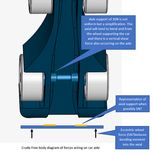
When I look at your Static 3 sim it looks ok, for your modelling assumption of a uniform 10N load over the axial with supports at the ends. The stress and deflections seem ok, from a gut feel perspective, whilst looking at the exaggerated deflections and the associated Von Mises Stress. But I suggest the simplification is not what is happening in reality, but your modelling assumptions may produce a worst case stress and deflection situation, which is a conservative and simpler approach & maybe what you have been given for the model.
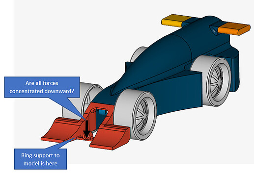
Ok, mine image of the car point loads and supports possibly too detailed, but here is a consideration of the forces that may be acting on the rear car axle, but this again is a simplification of real life where a motor would induce torque forces. Anyhow Static 3 simulation seems ok.
Static 4 - Seems ok for simplifying assumptions
Stress and deflections seems ok, gut feeling assessment.
You may wish to look at another stress criteria other than the Von Mises Stress if you wish to focus in on the shear stress. Your model of 10N force on the upper side of the front wing airfoil is consistent with your axle wheel load.
You boundary conditions and forces applied seem ok, so I would be happy with your results, but again I have not applied any calculations to the model.
- Simple beam Bending stress My/I ie (applied Moment time distance from neutral axis)/ Moment of Inertia, tensile forces
- Average tensile or compressive stress is it below the material allowable stress Force/Cross-sectional area
Global considerations.
Three matters civil engineers tend to look at Strength, Stability and Serviceability (deflections)
Now stand back and look at your model for stability considering the loads and deflections, what happens to the total car? You have looked at the individual components, but will the car kick up at the back due to the imposed 200g load imposed at the front, will this cause instability, is there a rear guide. Anyhow what I’m saying is don’t forget to look at the whole car for stability from the imposed forces.
Good luck, I’m only a novice Simscale person but you seem to have got the simulations correct as far as I can see but the biggest issue is likely to arise I’m assuming from the 3D printing components & connections of PLA if this is the way your are going, especially small components and attention to the layering and smoothing by the use of fillets is crucial for strength. ( anisotropy is defined as the material’s tendency to react differently to stresses applied in different directions)
Well, let me say I’m very impressed with the efforts so far from your team.
Regards
Ted

