Im currently developing my bachelor final thesis, and Im basically analyzing a F1 front wing simple design to discuss the different effects of their parts.
My problem is that I do not know if I’m solving the boundary layer in a correct way. For the resolution of my model I’m using the k-omega SST turbulence model. I’ve talked with SBlock a bit about it but I keep having problems regarding inflation layers.
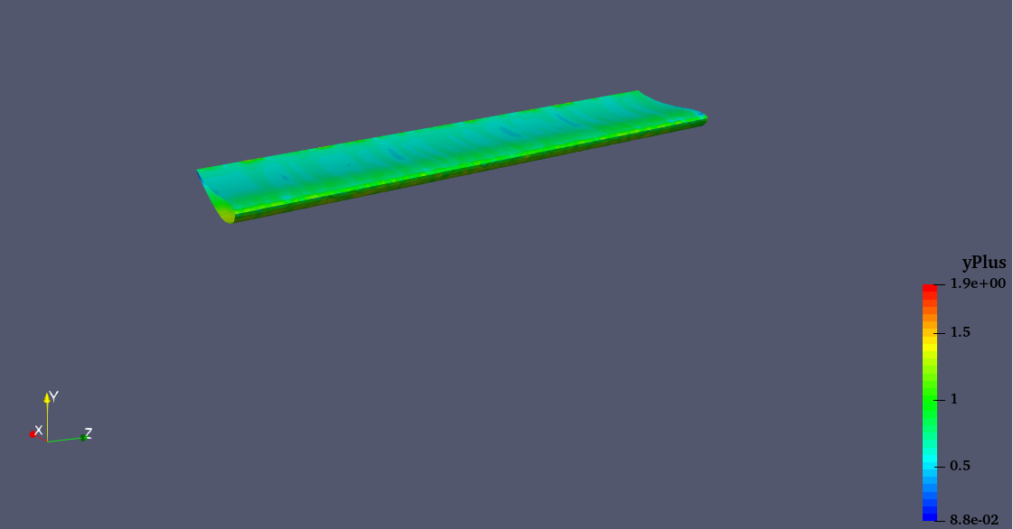
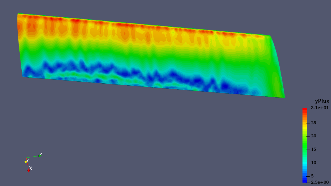
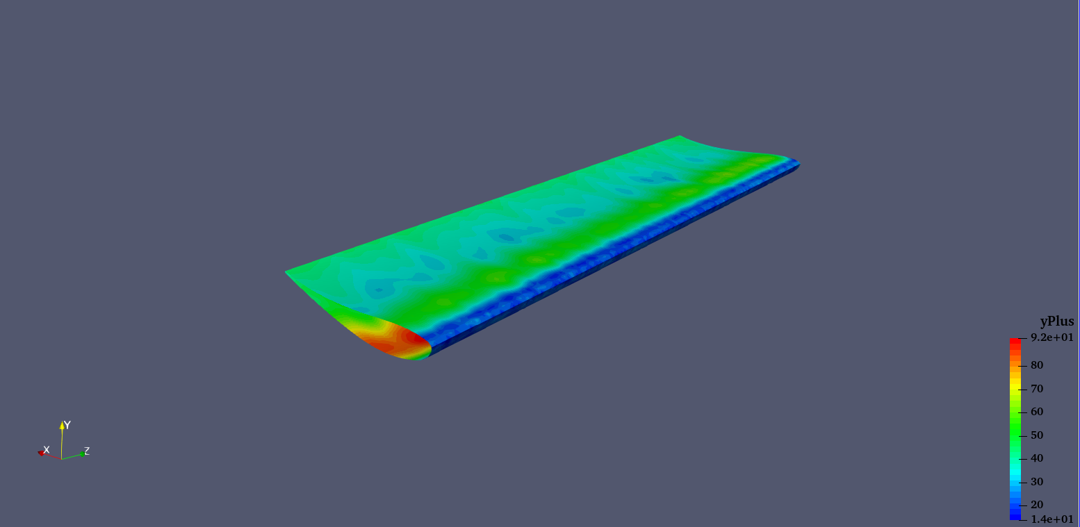
I’ve tried to y+ targets, 1 and 30. The thing is that I cannot manage to maintain this target values along my design. For the case of y+=1 I get the following y+ values:
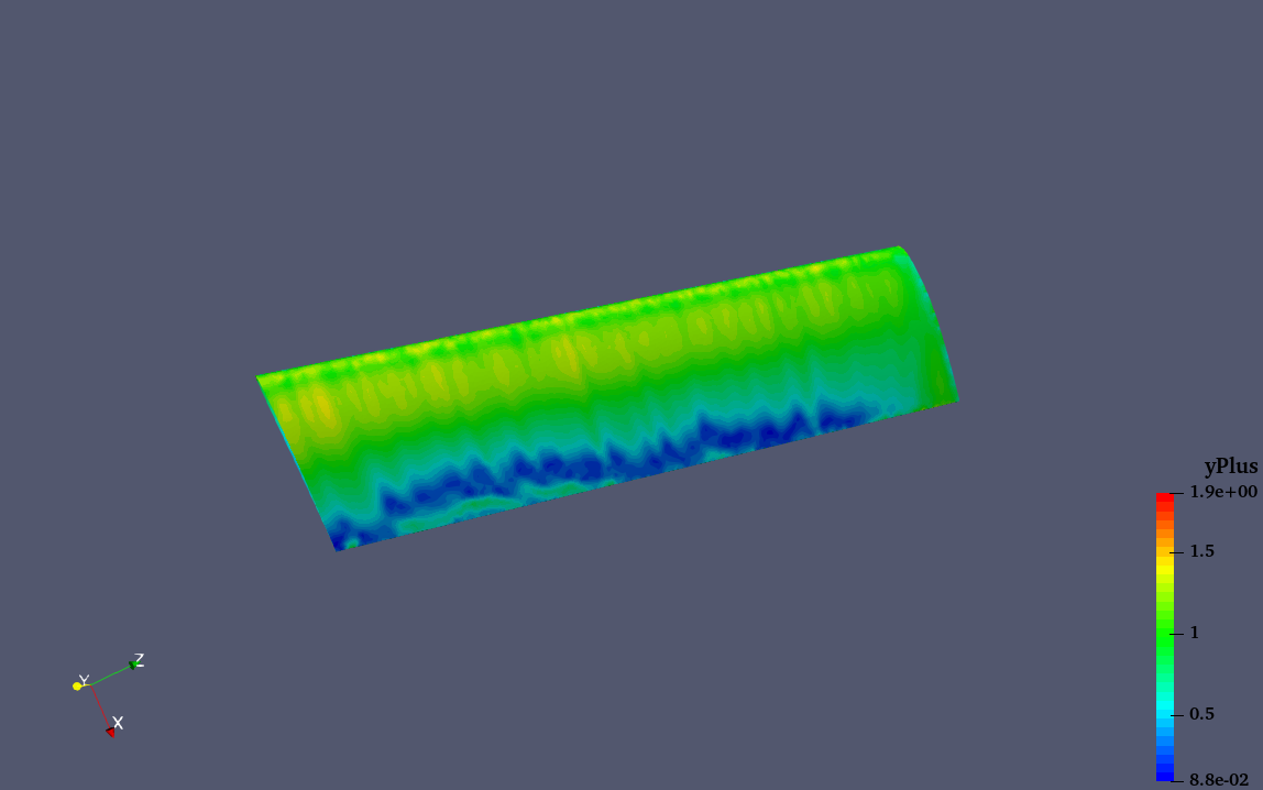
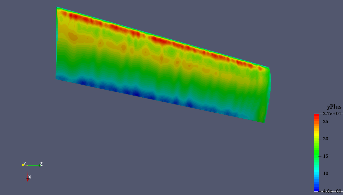
Further investigating and commenting with different people I tried changing the number of layers. For the above analysis I used: 20 layers for y+=1, and 15 layers for y+30. The reason for this was that this cool guy from youtube that many of you may already know “Fluid Mechanics 101” , stated in one of his videos that for y+=1 you have to use number of layers >25 and for 30<y+<300 a number of layers >15. Neverthless, I tried having 4 layers targeting a y+=30 and this was the result:
I don’t know what could be my source of error, maybe the overall mesh (I am thinking of developing an structured one). Having said that, any type of help is welcome as I need to finish my simulations or have something useful at the end of this week.
may I ask why do you want to achieve a Y+ of 30?
When having a look at this standard graph on u+ over y+. Please note that one area, the buffer layer, cannot be well captured by the turbulence model. Therefore you usually try to stay away from this region.
So your Y+ values should be in a range from either 0-3, or 30-100.
When having a look at your last image, you are exactly in the buffer layer.
therefore I would recommend you to choose 2-3 Layers and try to achieve a mesh in the range of 30-100.
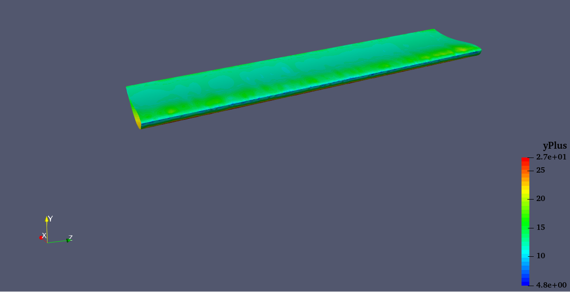
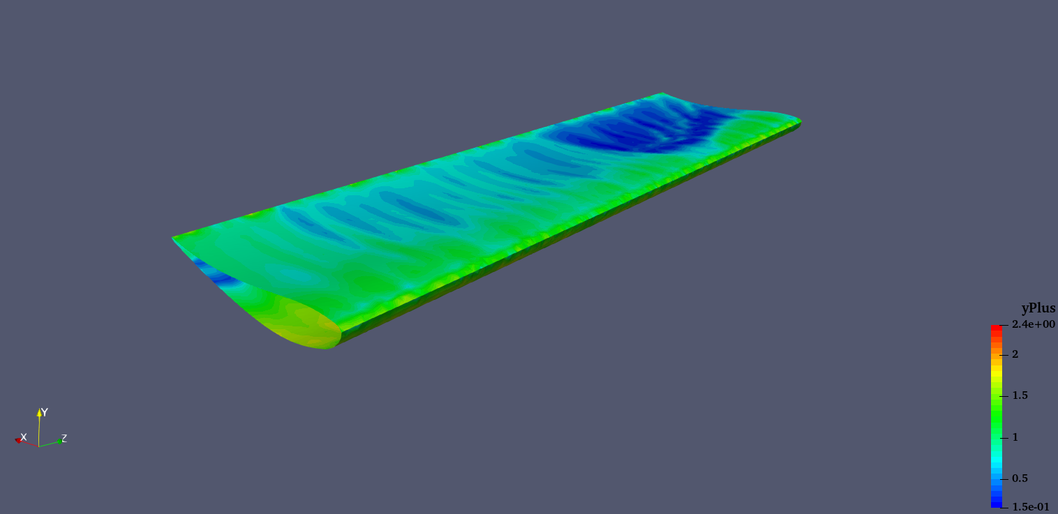
Yes, this looks better, but can you please have a look at the surface mesh of the Wing to see if this ununiform y+ is related to the mesh. I’m 90% sure it’s mesh-related.
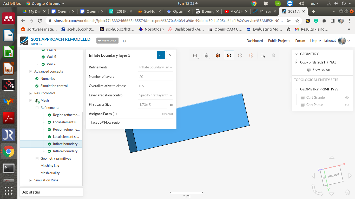
If you only set the number of elements, the first layer element will still have the same value, therefore the behaviour will be similar with 20 or 5 elements. So what you need to do is set a thicker first element.
Still, regardless of what Fluid Mechanics 101 said, you will never achieve a specific y+ value with the values mentioned by him, but a rough approximation.
If you need to achieve a specific y+ value you need to calculate the boundary layer size and estimate the y+ 1 and y+30 sizes and set the first element to that size (or calculate it through relative layer size). Here the number of elements may be irrelevant
The calculation of the y+ value is not easy as your case is not a flat plate but a couple of simulations + flat plate calculations should give you a good approximation.
The y+ value will not be uniform through the airfoil as the boundary layer grows in size downstream (and in low-pressure regions downstream the maximum thickness point). Neither will it be the same in the upper and lower faces.
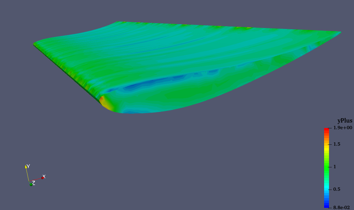
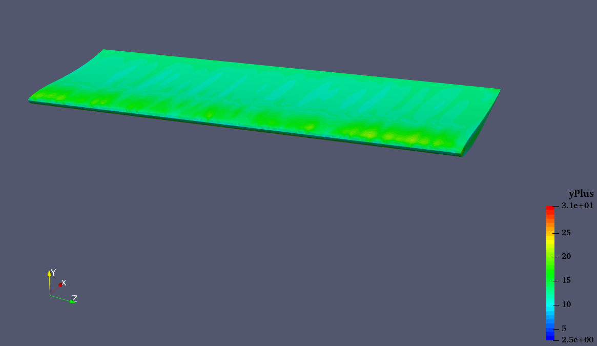
First of all thank you for your answer, I really apreciate when people help me without having the need to. To set some context, I am indeed trying to obtain a satisfactory resolution of the boundary layer in my wing. In my project (depending when you entered, I am changing many things) I am trying to just satisfy the conditions to reach a correct simulation. I have been trying to run simulations for y+ 50 and 1 and have obtained some results:
With respect to this comment, I am calculating everything with care I believe, taking into account freestream velocity, reference length, fluid conditions, etc…
I am currently trying this, for the case of y+ between 2.5 and 0.15 I will try lowering the first layer heigh by a factor of 2.5 to try reaching values lower than 1. However I believe that y+ values in that range should be sufficient right?
I hope I am explaining everything clear, and once again thank you for your answer. If you need anything else to know in order to help me please do not hesitate contacting me.
Dear Alex, you are right. You will never obtain the same value of y+ through the airfoil unless you use a very advanced layer mesher which allows us to control the first element size through the airfoil (or perhaps a combination of layer mesh parameters that I can’t think of at the moment) I am not sure if even the standard version of OpenFOAM has such capability. But you can decide where in the airfoil is going to be your reference point where y+= 1 or =50 is achieved and run all the simulations based on the same criterion. Depending on your “layer addition” configuration, the number of elements may be irrelevant to calculating the size of the first element from the wall, but still, use a good number to keep a smooth transition (1.15 or 1.2 relative size).