The project:
The goal:
Better understanding of a new Custom CFD boundary condition for pressure: Fan Pressure
Description of FAN PRESSURE custom BC
The fan pressure custom BC represents the situation where an artificial fan operates at a particular face.
It will create the pressure drop in the specified direction based on the flux/pressure curve. This means that the pressure drop applied on the face is dependent on the flow flux that passes through the BC.
Here is the documentation on how to set this BC up.
Geometry
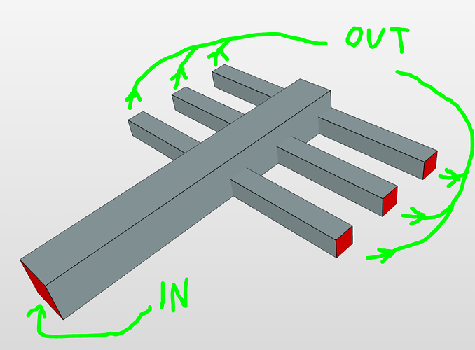
One inlet, 3x2 outlets. Symmetric
Mesh
Automatic snappyHexMesh: modetate, with layers at walls
- we could have taken benefit from the symmetry of the case, either by making “half” of the CAD, or by manual snappyHexMesh and making the bounding box cut the geometry in half. This is a concept project so with moderate mesh it was OK even with full geom.
Simulations
1) reference- moderate turb, out p fix
-
- as the name suggests a reference simulation
-
- velocity inlet: 0.1 m/s
-
- pressure outlets with fixed pressure: 0
-
- we aimed to calculate what will be the theoretical pressure drop in the system to have a range to generate a reasonable pressure curve
2) turb, p fan curve
-
- here we test the fan pressure boudnary condition
-
- all simulations are set the same except for the pressure BC at outlets
-
- the runs contain some unused artifacts like not-set BC. Ignore them
-
- velocity inlet: 0.1 m/s
RUNS:
2.1) out, positive pressure curve Run 1
- velocity inlet: 0.1 m/s
-
- pressure BC condition: Custom:
-
-
- Velocity: Pressure-inlet-outlet velocity
-
-
-
- k: zero gradient
-
-
-
- epsilon: zero gradient
-
-
-
- pressure: fan pressure
-
-
-
-
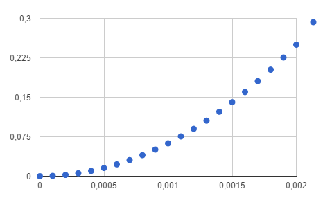
- the tabular values show a positive parabolic profile
-
-
-
-
-
- direction: OUT

2.2) in, positive pressure curve Run 2
- direction: OUT
-
-
-
- pressure BC condition: Custom:
-
-
- Velocity: Pressure-inlet-outlet velocity
-
-
-
- k: zero gradient
-
-
-
- epsilon: zero gradient
-
-
-
- pressure: fan pressure
-
-
-
-
- the tabular values show a positive parabolic profile
-
-
-
-
-
- direction: IN
-
-
2.3) out, negative pressure curve Run 3
-
- pressure BC condition: Custom:
-
-
- Velocity: Pressure-inlet-outlet velocity
-
-
-
- k: zero gradient
-
-
-
- epsilon: zero gradient
-
-
-
- pressure: fan pressure
-
-
-
-
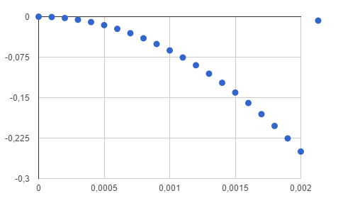
- the tabular values show a negative parabolic profile
-
-
-
-
-
- direction: OUT

- direction: OUT
-
-
Comparison of flux and pressure results:
Discussion of results
Obviously we will focus on the second simulation.
the fan curve represents the pressure drop created by a fan that operates in the direction
Run 1
- since our fan is operating as an outlet, we chose the OUT direction
- the flux/pressure curve has positive pressure values
- the BC interprets the flux/pressure curve as pressure drop created by the fan
- for this reason the pressure values at the outlets are negative
- in this case the virtual fan operates as follows: the bigger the flux, the bigger pressure drop it creates
Run 2
- we kept the same pressure curve and changed the direction to IN
- since the BC expects to operate as inlets, it sets the pressure values as zero
- run is basically the same as the reference
- the specific BC did not work at all
Run 3
- the direction is again set properly to OUT
- this time we introduce a flux/pressure curve with negative values of pressure
- in this case, the fan creates resistance (increased pressure) with higher flux values
- this setup can be used to model virtual flow obstacles (diffusor, long piping segments, etc) that will “slow down” the flow when its flux gets higher- like a choking mechanism
Some final words
Hope that this topic brought some light to the new BC type available for pressure. Do let me know what you think of the project. I am glad to answer your questions if you have any.
Good luck with your projects!
Best,
Pawel

