@Maciek, awesome! I am right now waiting for my current simulation to finish (takes quite some computing time these multiphase flow simulations … ) and I’ll then get back to you! Thanks for helping!
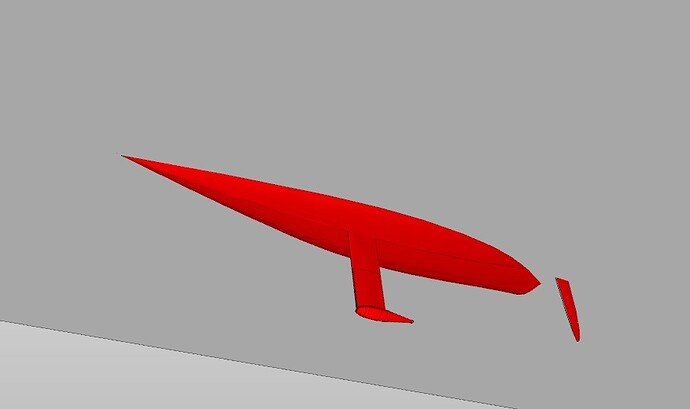
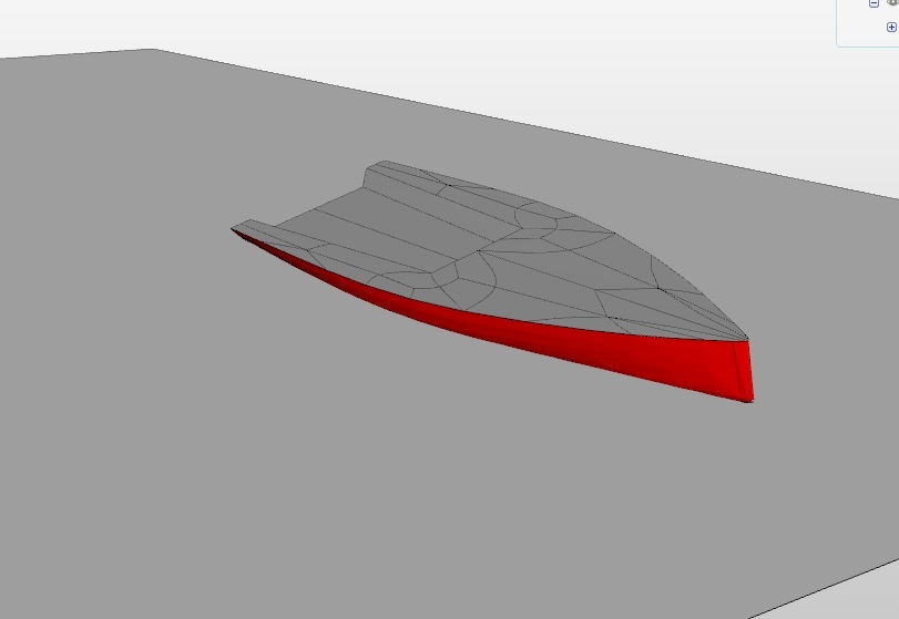
Hi dheiny, I have strong interest in this case and want to collaborate (if possible). A few suggestions on your simulation: your hull is too much immersed under water surface. As a roughly guide, water plane should pass through the inflexion point at the bow. Another important feature to include is heeling angle. Most of the time a sailing yacht will sail at a heeling angle, particularly when she goes against the wind. Normal angles can vary from 5 to 15 degrees.
I can provide you many geometries in .step or .iges format for you to include in a simulation tutorial of sailing/motor yacht hulls at different displacements and heeling angles.
I think calm water and steady state (fixed velocity) is a good starting point for this kind of (heavy) simulation.
Hi @quequen,
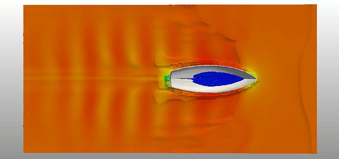
looking forward to collaborate! The boat in the image is simulated at 1 degree heeling angle, but it’ll be fairly simple to increase it to a larger value. Thanks for the hint with the water surface level - will take care of that as well. I paused the project for a while as I was waiting for some new functionality on SimScale, making such a simulation easier to set up, which just became available. So I would now continue to work on it. How about we use one of your geometries? A STEP model would be great. If you upload it to a SimScale project and share it with me, we could work together on this.
Best,
David
Hi David, I shared a project having a sailboat hull with appendages. Please let me know if you find issues, I’ll try to fix them…
I see now that my limit of storage for my free academic licence in Simscale is just 2MB, perhaps that’s the reason for the low quality of my .step file? It looks pretty poor on Simscale, while in other softwares it looks better.
neat, thanks!
The academic plan comes with a much higher storage limit (50GB, see the academic plan on Plans & Pricing | Professional, Team & Enterprise | SimScale), so this should not be the reason. SimScale uses the native data you provide (in this case, the STEP file) for downstream processing (e.g. meshing) so the “data quality” is not changed withing SimScale. Depending on your CAD system, what can happen is that the STEP export does something unexpected (e.g. check on @BenLewis’s post). What exactly do you mean by poor? The tessellation of the surfaces? That might be due to optimization methods we are using to accelerate loading and interaction - but it’s just related to visualization.
Thanks for sharing the project, will look into it this week and get back to you. Once we are done, would you be fine with putting it as an example in the SimScale library? If yes, we could ask @sjoshi if he would like to join this project. He is currently working on a similar project for the library and it might be a piece of cake for him to set this up.
It would be great to have this simulation as a part of the library! In case you would like to publish this project, or have any issues with the simulation, please share the project here.
Meanwhile, like @dheiny said, I’m working on a similar project. As soon as I have some results, I’ll update here.
@sjoshi, it will be nice if you can join this project too. I’ll be glad to see this project in the library, you can use the geometry freely, it’s of my own, so no copyrights involved.
Any tips on how to define the 2 phases?
@dheiny, seems like something happened with my account when I subscribed to the forum, now it is a basic account and no longer an academic one… can it be fixed?
It will be great if Simscale accept .iges files, they are easier to handle.
I have many doubts on the geometry:
Must the water plane go into the hull? My waterplane is cut by the hull skin, it has a hole where the hull lies. I don’t know whether is it right. I’ve seen many simulations where waterplane goes into the hull.
Must the hull be splitted by the waterplane? Mine isn’t.
Thank you! I’ve requested access to your project from @dheiny, and will begin work on it soon. Meanwhile, I’ll try and address some of your questions.
seems like something happened with my account when I subscribed to the forum, now it is a basic account and no longer an academic one… can it be fixed?
I think the following procedure should give you access to the academic account:
- Log in to your SimScale account.
- Click on the My Account button (located on the top-right of the platform interface)
- Click on Upgrade Plan button. This will take you to a new page.
- From the two tabs (Commercial and Academic), select the Academic tab.
- You should be able to select the Academic Plan then. In case the problem persists, @agata could help you out.
Any tips on how to define the 2 phases?
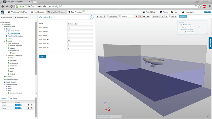
Sure! Once you create a new simulation, the initialization of the phases can be done using Geometry Primitives ([details here][1]). Geometry Primitives can be specified under Simulation Designer → Simulation → Domains → Geometry Primitives
How it works is, in the Phase Fraction part of the Initial Conditions tab, we switch to Subdomain-based option. Then, we specify the Default Value of the phase fraction. This initializes the entire domain to that value of the phase fraction (say 0).
We can then use a previously defined Geometry Primitive (lets say we use a Cartesian Box), to initialize only that part of the domain which is occupied by the box to the other phase fraction value (in this case, 1).
Must the water plane go into the hull? My waterplane is cut by the hull skin, it has a hole where the hull lies. I don’t know whether is it right. I’ve seen many simulations where waterplane goes into the hull.
You are right, it is not exactly how one would want their boat to sail as ![]() , and we are looking at introducing more specific ways of initializing the domain in the future.
, and we are looking at introducing more specific ways of initializing the domain in the future.
But I think it does not affect our simulation to a big extent. This is because we are not including Fluid-Structure Interaction, and hence presence of water in the boat does not affect the buoyant forces on the boat. It does change the movement of air inside the hull cavity - which can be safely ignored if the focus is on drag and wake studies on the outer surface of the boat.
One workaround could be to fill the inner part of the boat with solid material, so that it is not counted as a part of the domain.
[1]: SimScale Documentation | Online Simulation Software | SimScale
@quequen, I checked you account history and it seems you just subscribed to the premium test on August 1st. Feel free to upgrade to Academic anytime and enjoy the full power of SimScale! Let me know if you have any trouble.
thanks @vdoelle1, @sjoshi, I updated my account to Academic.
Have you considered to save a small tutorial to explain the settings?
Can the Documentation be downloaded as .pdf?
Have you considered to save a small tutorial to explain the settings?
@quequen, I am currently in the process of wrapping up the simulation in a state that can be shared. Once that is done, I will share the simulation here and it can then be imported in your library.
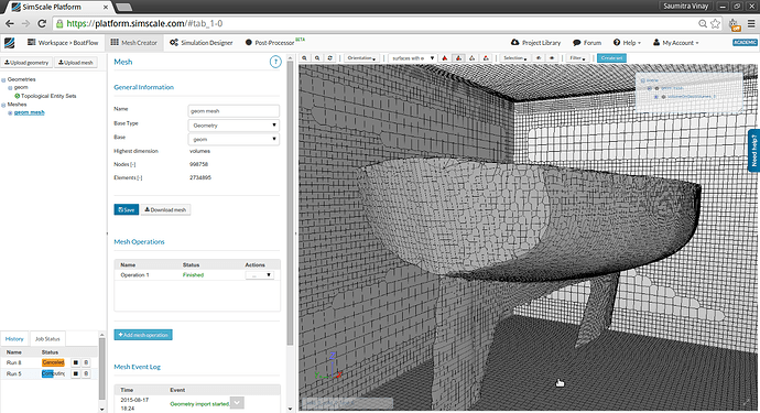
We have some results: the geometry for now is the original one that @dheiny used. It was initially refined to a high level of detail, but the element size there was too small for the simulation to finish stably in reasonable amount of time. So the mesh was coarsened a little.
The boat sails at a speed of 2 m/s, and I ran the simulation for about 38 seconds of simulated time. Here is an animation of the interface. We can clearly see the formation of a stable wake over time.
Fast progress @sjoshi ! If your boat travels at 2m/s then it seems to sail at Fn=0.23 Distance between wave crests should be about 2.56m and your LWL should be about 7.7m
Are this values close to reality?
Transverse wave system seems ok, however I would expect a divergent wave system more clearly visible. Perhaps domain width is too small?
Why are the highest waves flattened on their crests?
I think I’ll wait for your simulation to be finished before making more attempts with mine, too many things to learn yet !.
@quequen
Thank you for the data! I did some quick calculations. The Waterline Length l_{WL} of the boat is 6.7 \text{m}. Based on the relationship between hull-speed u_{hull} and l_{WL}:
$$ u_{hull} = 1.4393\sqrt{l_{WL}}=3.73\text{m/s}$$
So I think I’ve underestimated the speed! The Froude number can be computed as
$$ Fr=\frac{u_{hull}}{\sqrt{g_0 l_{WL}}}= 0.46$$
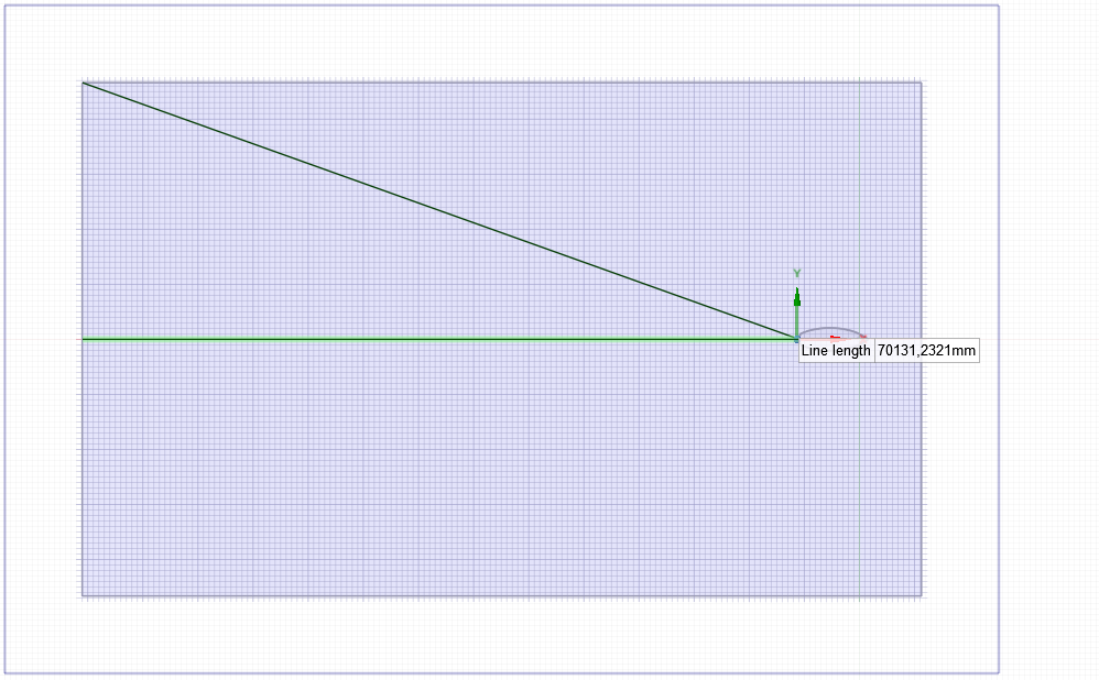
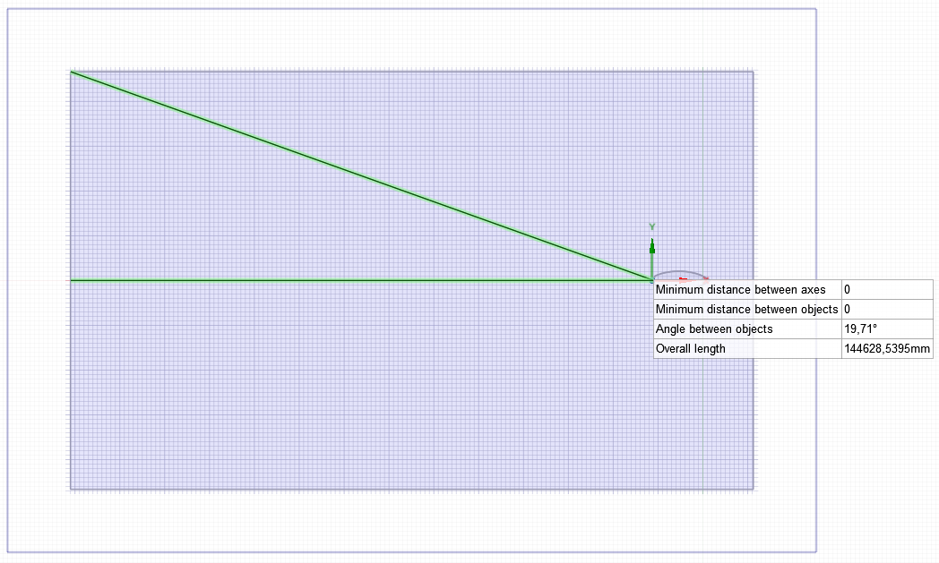
According to [references] (http://www.prirodopolis.hr/daily_phy/pdf/speed.pdf), the wake angle \theta_w for boats travelling at hull-speed is usually 19.5 degrees. Assuming we’re interested in a wake region that is approximately 10 times the l_{WL}, I’ve modified the domain size to include the entire potential wake region. I’ll now run a simulation with the right speed and geometry bounds, and will update with results soon!
Thank you once again for the observations. This is exactly why forum discussions are so productive. ![]()
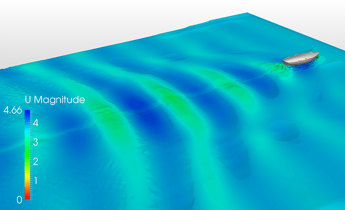
Based on @quequen’s suggestions, I modified the domain size and supplied the correct input velocity. I ran a short 3 second simulation just to see how the wake starts developing, and it already looks much better than last time.
Waiting now for a 20-seconds run to finish.
Wow! now the transverse wave system is cool, showing his typical curvature. Diverging system still don’t appear.
Check depth, shallow waters (assuming non-adiabatic walls of the domain) should have a strong effect on wake, even making the transverse system disappear. But even then, the divergent system should be there (Edit: but not in the same way! ).
Distance between crests now concur with Fn=0.46 (slightly longer than LWL). Although Fn=0.46 is pretty high for the kind of hull you are analyzing. If the hull has not vertical freedom, it will lead to error because the amplitude of the wave under the hull will make the yacht “lighter” (less water displacement than really needed). There is a way to simulate this in a more realistic way: sink the hull slightly at the beginning of simulation so that, when at Fn=0.46 , the water volume displaced by the hull still equalls yacht’s weight.
About Kelvin wedge, some concepts can be considered beforehand:
Divergent system is always there, no matter the yacht velocity, hull shape or water depth, (Edit: but it can widen a lot in shallow waters!) .
Transverse system appears at low Fn up to, say, 0.6 At higher Fn the hull may be planing and then it dissapears completely.
Transverse system can dissapear in shallow waters even at low Fn.
The tangent angle inside the divergent system isn’t constant: It goes smaller when Fn goes higher.
Longitude of transverse waves is proportional to yacht velocity only.
Amplitude of transverse waves is proportional to yacht velocity and yacht displacement, and may be affected by hull shape.
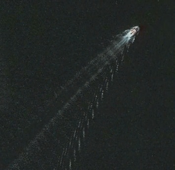
Typical Kelvin wedge behind a ferry, traveling at about Fn=0.3 or 4.9 m/s (taken from Google Earth)
LWL: 26.5m
Distance between transverse waves: 19m
8 second Simulation visualization. As per @quequen’s observation, for Fr=0.46, both diverging and transverse wave systems appear in the beginning but then are lost - probably because the domain is still too small.
Now running a simulation with domain four times as big.
