Calculating volumetric flow rate through porous media

Hello. I’m trying to evaluate the flow rate of air through a formula SAE style radiator and I’m having some trouble with the results and general understanding of how it is calculated.

The link to the project is: carenagem teste - Copy by juliotz | SimScale

I’ve followed the simulation setup provided in the following link: Tutorial: Incompressible Flow around a Formula Student Car. The radiator is set up as a porous media, and I’ve used the same Darcy-Forchheimer coefficientes, changing only the normal vectors according to my FSAE team’s radiator position.

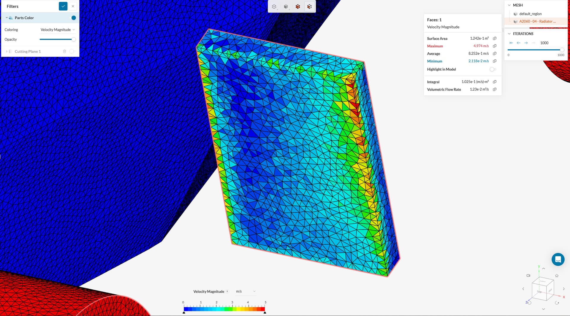
When setting up the simulation, I’ve followed a few different approaches, being using the same mesh refinements as the car surface for the porous media and using a Extrusion mesh to control the number of cells across the radiator’s thickness. The issue comes when post-processing the results.

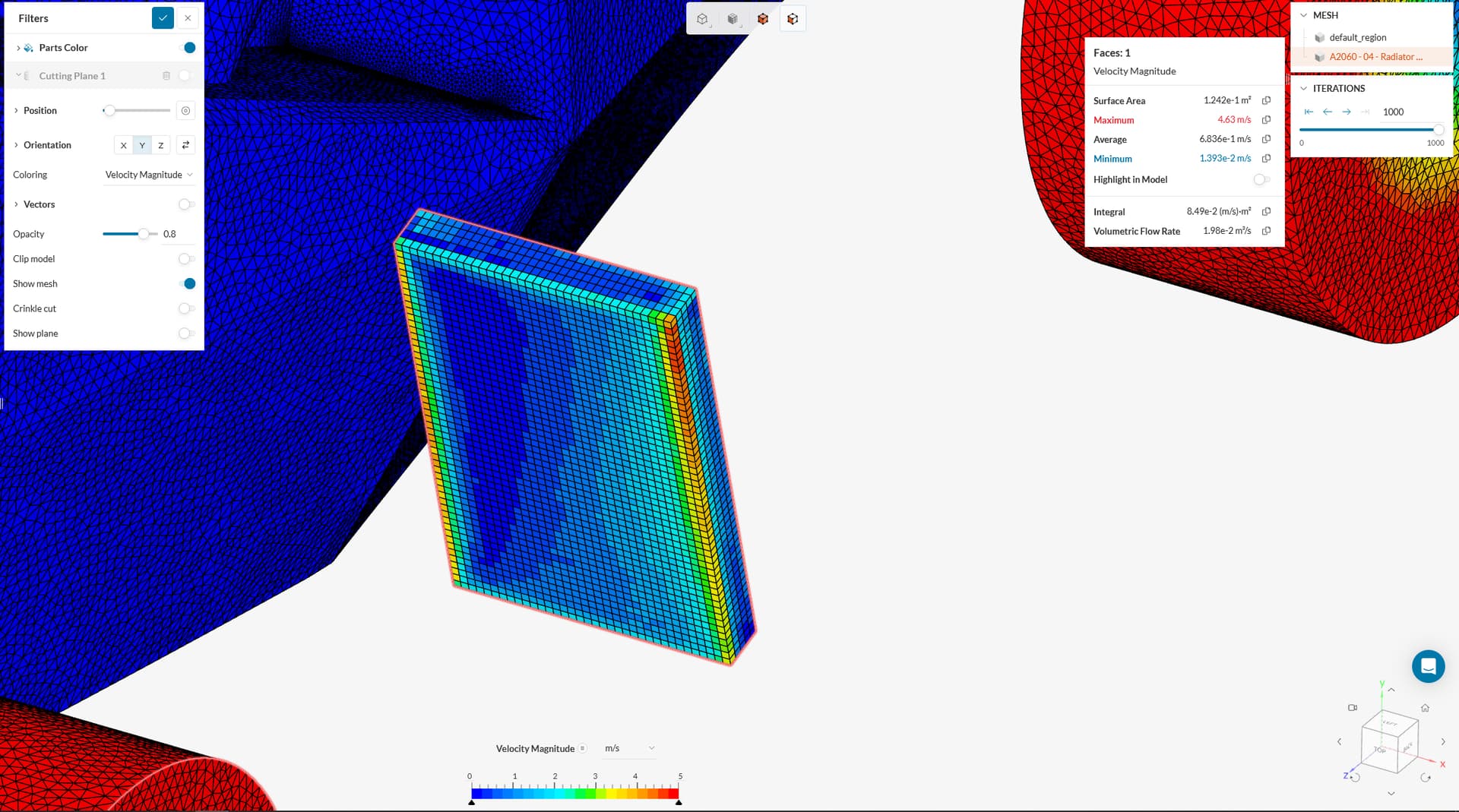
When checking the solution fields and isolating the radiator, there are a couple of things that are confusing me:

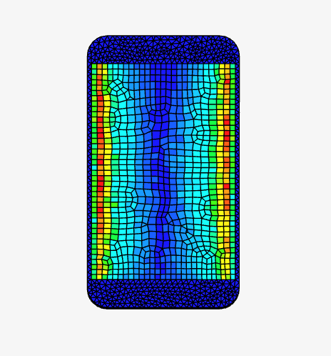
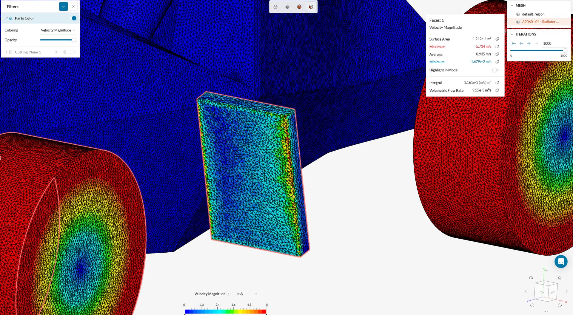
  1. When the porous media is selected, the geometry is considered as 1 volume, when there are 6 faces to it (front, back and sides);
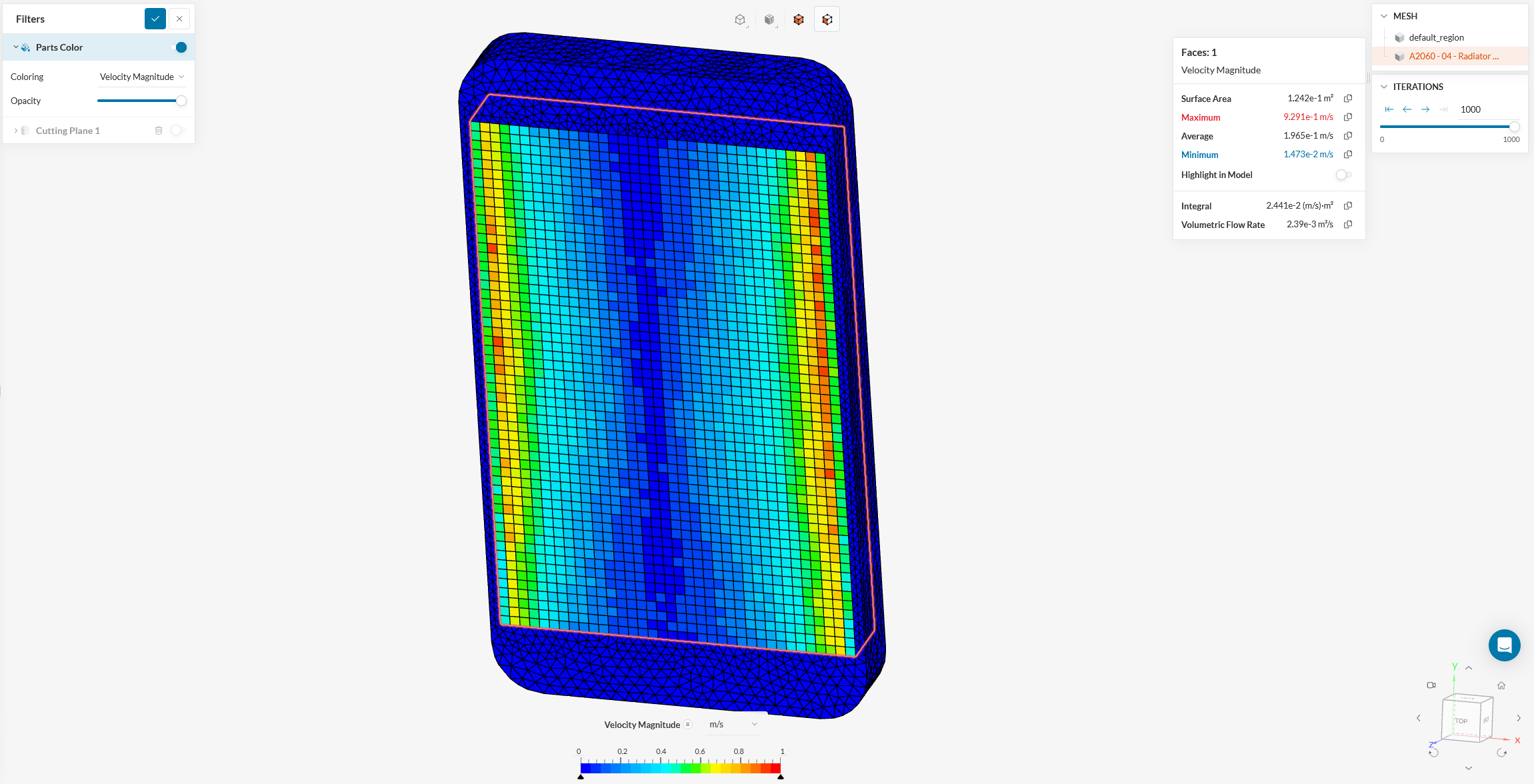
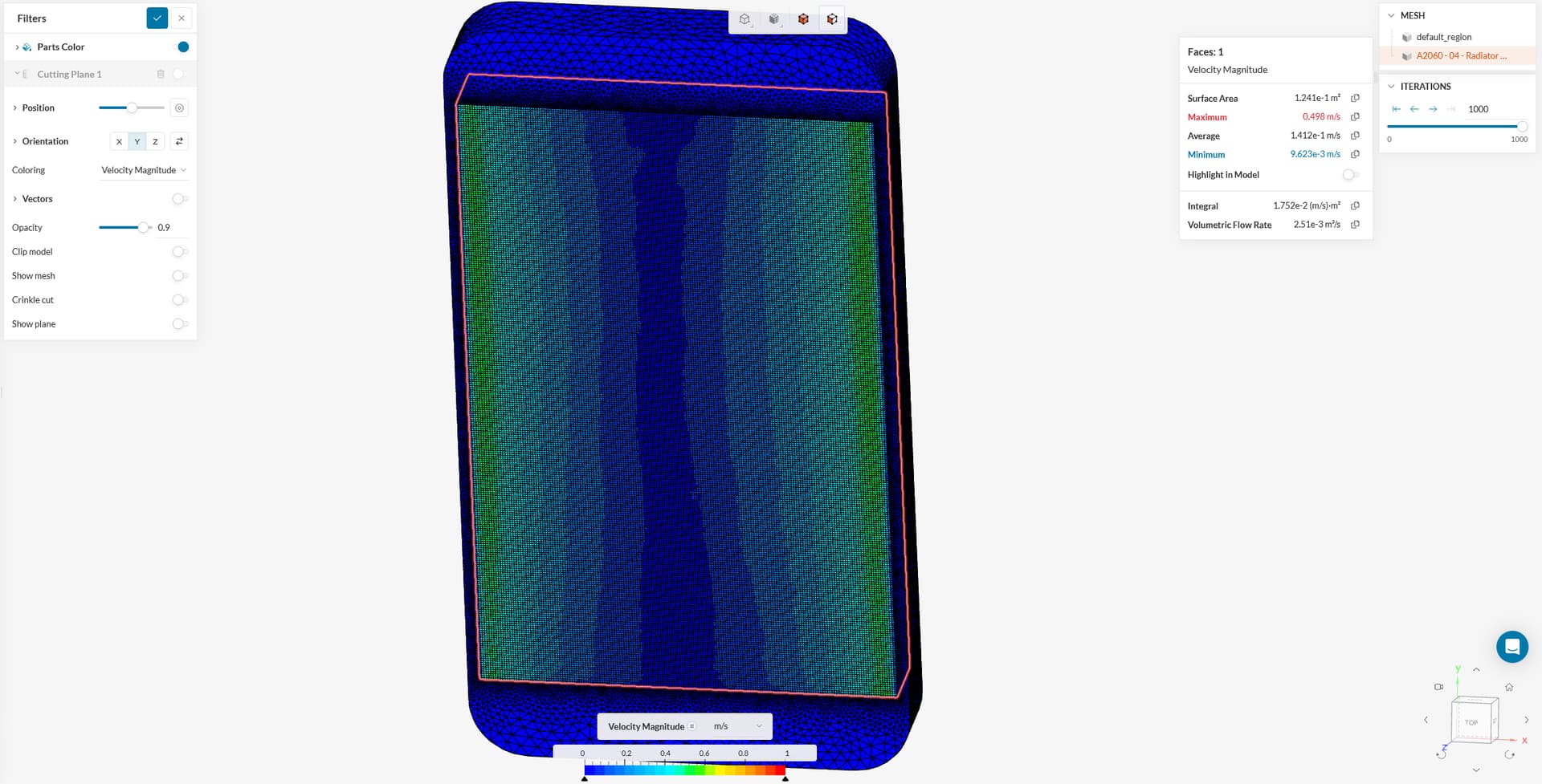
  2. The statistical value calculated of volumetric flow rate varies significantly across different mesh refinement settings.


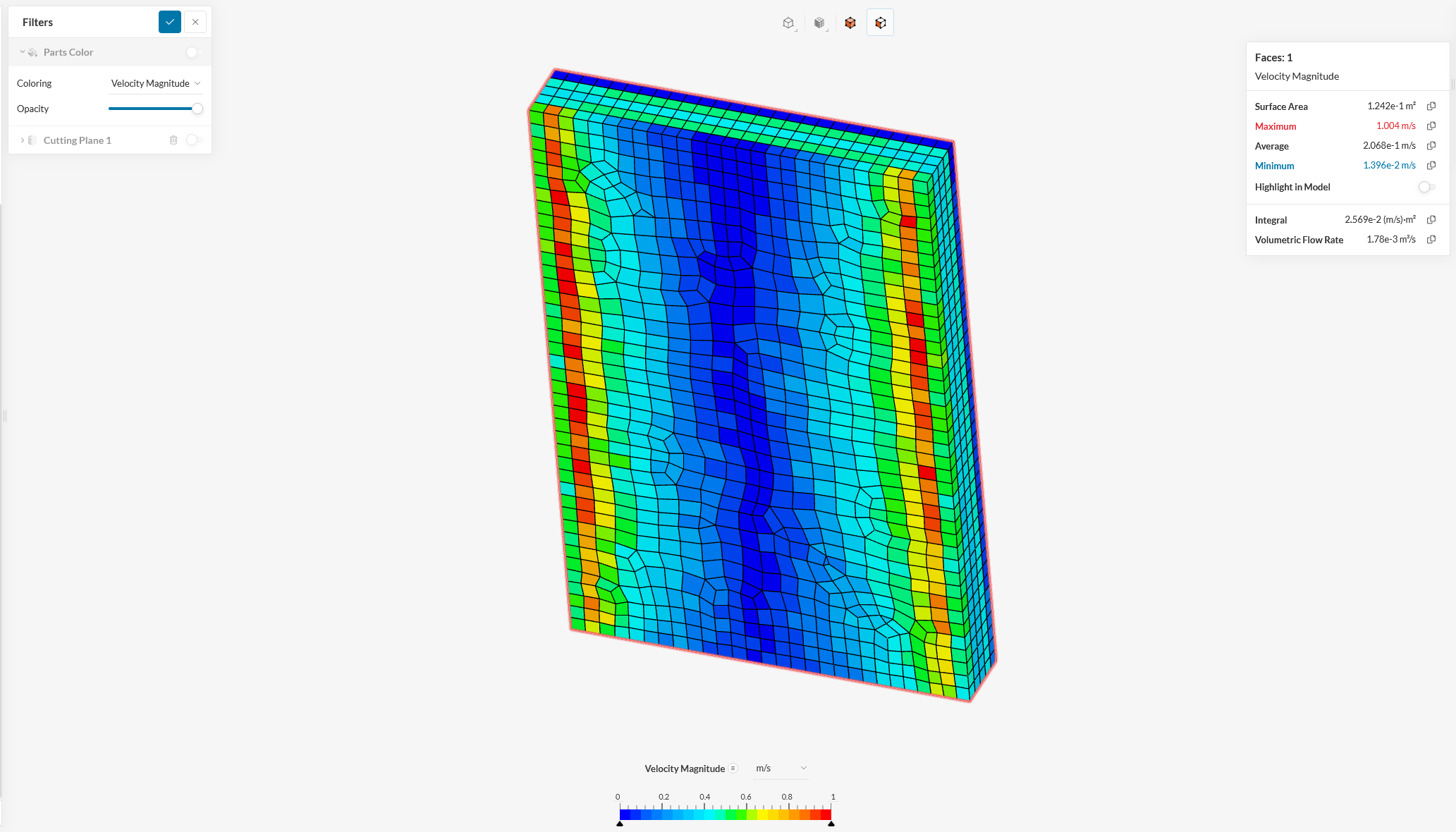
One of the simulations ran (run 2)

Is there anything wrong with my methodology?

Hi @jtramontina, thanks for posting on the forum :slight_smile:

I’ll try to answer each of your questions.

  • This is probably due to the fact that porous media is an advanced concept. Those only define a cell zone (therefore a volume) within the domain where the specific condition is applied.
  • I see that the mesh you’ve created seems to be of very low resolution:

image

In that case, it would be worthwhile running some sort of mesh sensitivity study to evaluate which fineness is ideal in your case.

As a sidenote, I see that you’ve ran other studies, did they show you different results? Please share with us!

Best,
Igor

Hi Igor, thanks for your reply.

I’ve ran a few different studies. I’ll try to summarize my findings in a sequantial way so that you can get the whole picture.

At first, I’ve imported the whole geometry (car + radiator as e porous media) and used the same mesh refinement for the surface of the car and radiator. The results are as follows:

In this case, as you can see, the radiator is purely a rectangle, with no shroud.

Then, I ran a study with a coarser mesh to see if it had similar results:

Then, I read a page of the documentation that said we should have at least 5 cells thickness wise, so I changed the meshing strategy for the radiator and ran another model using the same meshing refinements as the above here, but using a extrusion mesh for the radiator:

As you can see, the volumetric flow rate results are pretty far apart, even the velocity range is quite different. So I ran another study using the same mesh as the above with a finer radiator mesh:

With those results and some analysis, it made me wonder how is the flow rate evaluated. As the radiator is a single volume, it seems to me that the solver calculates all the flow entries in the cell and sums it up. That means that air can come from the sides as well, hence the red areas on the sides and blue areas around the middle.

That made me think that the problem (geometry) was oversimplified, because the car’s radiator in reality has a shroud around it, allowing air only through its front and back. So I’ve isolated it and imported the geometry of the porous part and the shroud as a non slip wall. I’ve simulated three different mesh sizes for the radiator, maintaining the enclosure and radiator shroud with a fixed mesh:

Coarse mesh:

Middle mesh:

Most refined mesh:

The coarse mesh has a very different result, but the finer meshes are showing some form of convergence.