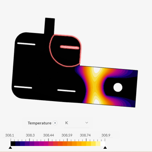
I’m trying to model heat transfer in a battery busbar. The mesh generates and the heat distribution pattern looks plausiable, but the magnitude of the heat transfer is much less than expected (less than 1 degree from the starting temperature of 308K carrying 65A). What am I missing? I was also expecting to see Joule heating between the individual battery cells. Thanks in advance.
Screenshot:
Link:
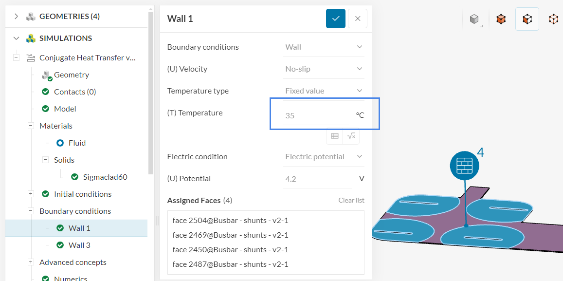
You’d likely have to change your boundary condition strategy, as you are currently fixing the temperature of faces to 35 °C:
PS: the other boundaries without an explicit boundary condition are currently adiabatic. I’m mentioning in case this is not intentional.
Thanks can I clarify the correct boundary conditions though? I’m trying to model just the Joule effect, with no free convection as a simplification. I understand that I need at least one fixed or natural convection boundary, but I’m not sure how that should apply in this case.
Also, is there any extra information about the electrical potential boundary condition? I couldn’t find any and I’m not sure what role it plays in the simulation, as I thought the heat loss should only depend on the current which is already defined.
A fixed temperature is going to act as an infinite source/sink of heat (depending on the temperature of the surroundings). As the name suggests, the temperature will be fixed to the value that you set no matter what is happening in the domain.
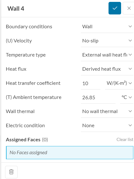
Of course this depends on your physics, but normally you’d see temperature definitions like this, which uses Newton’s law of cooling.
The electrical potential BC is just a reference potential. If you have a single current in, you’d normally go for current in + electric potential on the face where the current goes out.
Cheers
1 Like
I fully agree with @RicardoParis
You need to find an appropriate BC for your model problem. Particularly, I find this problem very difficult to model in a simplified way, as the heat generated due to Joule heating is transferred to the air by convection and to the battery itself and upstream connectors by conduction. Wrong assumptions here will result in incorrect energy fluxes and therefore erroneous simulated temperature measurements.
So, if your goal is to determine the final temperature of the busbar, you need to model the whole system where the heat is being transferred to and dissipated (battery and cables), at least in a very simplified manner, and include convection. The supports of the battery may indeed use fixed temperature BCs.
One question: why is that 1 ºC temperature difference unexpected? The busbar should be a good heat conductor, which would dissipate this heat quickly to the battery and upstream cables. Do you have any measurements or mechanistic calculation values? Remember, one thing is the temperature delta, and another is the “simulated temperature,” which naturally may be wrong.
1 Like