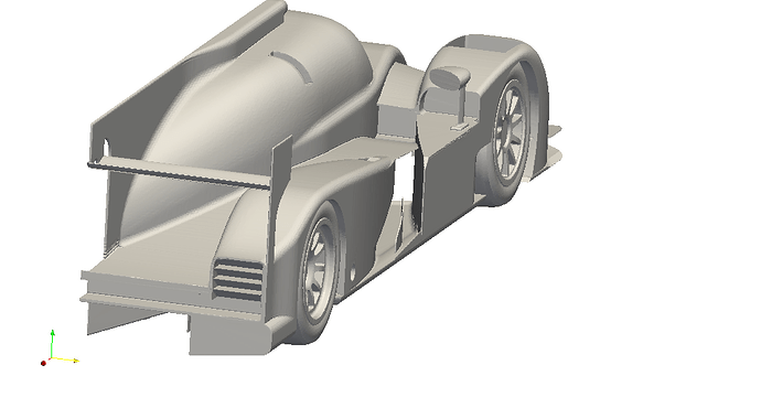
Aerodynamics of Perrinn LMP1: Investigating the drafting and overtaking conditions as well as driving in a Yaw angle

The fine mesh won’t run because it has failed checkMesh:

Checking geometry...
    Overall domain bounding box (-11 -0.000530918 -0.0375) (39 11 11)
    Mesh (non-empty, non-wedge) directions (1 1 1)
    Mesh (non-empty) directions (1 1 1)
    Boundary openness (-3.61347e-16 5.91293e-15 -2.25693e-15) OK.
 ***High aspect ratio cells found, Max aspect ratio: 1.82536e+195, number of cells 10
  <<Writing 10 cells with high aspect ratio to set highAspectRatioCells
    Minimum face area = 3.95633e-09. Maximum face area = 0.071144.  Face area magnitudes OK.
 ***Zero or negative cell volume detected.  Minimum negative volume: -9.07755e-09, Number of negative volume cells: 10
  <<Writing 10 zero volume cells to set zeroVolumeCells
    Mesh non-orthogonality Max: 175.416 average: 8.48142
   *Number of severely non-orthogonal (> 70 degrees) faces: 37.
 ***Number of non-orthogonality errors: 15.
  <<Writing 52 non-orthogonal faces to set nonOrthoFaces
 ***Error in face pyramids: 74 faces are incorrectly oriented.
  <<Writing 66 faces with incorrect orientation to set wrongOrientedFaces
 ***Max skewness = 104.595, 368 highly skew faces detected which may impair the quality of the results
  <<Writing 368 skew faces to set skewFaces
    Coupled point location match (average 0) OK.

Failed 5 mesh checks.

The more the stars, the worse the problem. But it is I believe the negative cell volumes that kill the job.
The coarse mesh ran because checkMesh only returned:

Checking geometry...
    Overall domain bounding box (-11 -0.000567249 -0.0375) (39 11 11)
    Mesh (non-empty, non-wedge) directions (1 1 1)
    Mesh (non-empty) directions (1 1 1)
    Boundary openness (-6.24213e-17 3.15063e-16 1.35568e-15) OK.
    Max cell openness = 4.33442e-16 OK.
    Max aspect ratio = 38.3736 OK.
    Minimum face area = 1.5103e-07. Maximum face area = 0.273126.  Face area magnitudes OK.
    Min volume = 6.08063e-09. Max volume = 0.132627.  Total volume = 6068.62.  Cell volumes OK.
    Mesh non-orthogonality Max: 64.977 average: 8.98473
    Non-orthogonality check OK.
 ***Error in face pyramids: 1 faces are incorrectly oriented.
  <<Writing 1 faces with incorrect orientation to set wrongOrientedFaces
 ***Max skewness = 15.2136, 131 highly skew faces detected which may impair the quality of the results
  <<Writing 131 skew faces to set skewFaces
    Coupled point location match (average 0) OK.

Failed 2 mesh checks.

High skewness may or may not affect convergence/accuracy depending where the cells are located. If they are in regions with low gradients they are fine. There is only one wrongly oriented cell, which may also be located somewhere with low field gradients; maybe that’s why the case converged.
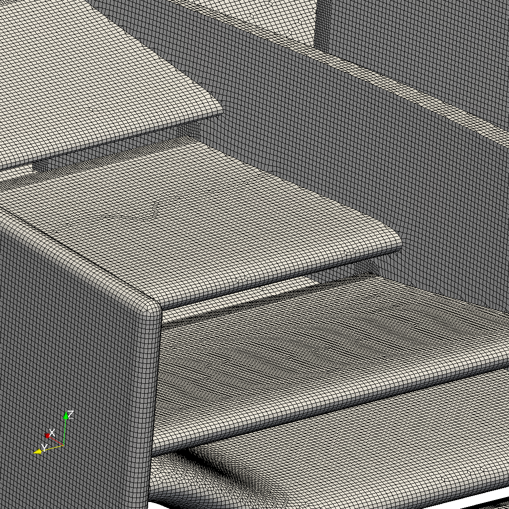
@dylan - good catch. Negative volume cells are indeed a show-stopper for the sim.

Now, lets talk about meshing with cut cells. For a complicated geometry like a racing car, you would want to split the stl file into multiple files and apply name-based local refinement. This way you obtain not only a better control over local cell sizes, but also a better capture of important edges as now patches/subsets along with their shared boundaries are recognised by the mesh generator. Finally, it is much easier to grow boundary layer cells on a good surface mesh.

Currently, surface split is easily done in native OpenFOAM with a collection of its utilities for surface mesh manipulation. I haven’t noticed such functions on the SimScale platform with a community plan.

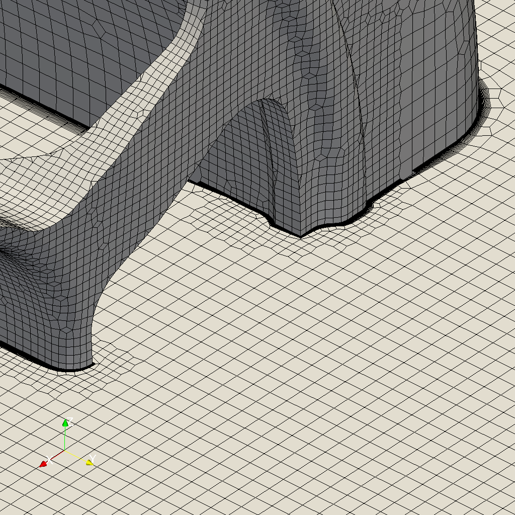
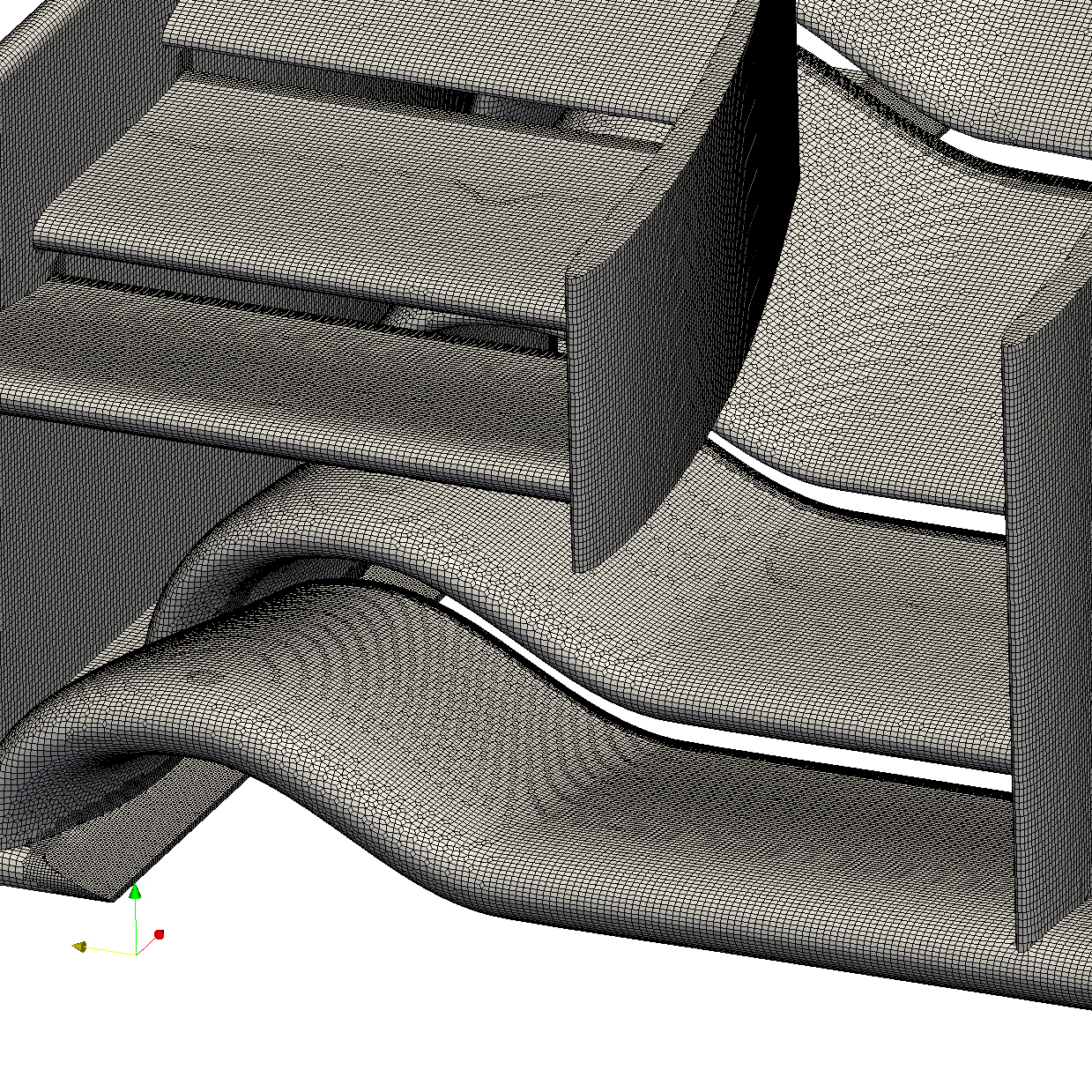
I have meshed multiple automotive/motorsport parts with structure/unstructured cells and am currently doing a PhD on aeroacoustics. I have found it very handy to let CAD do the hard work, although for relatively small/simple motorsport parts, splitting an stl file in native OpenFOAM can save me some time. An example of the F1 front wing from an early workshop SimScale organised is provided below:


whose checkMesh returns:

Checking geometry...
    Overall domain bounding box (-4.5 -3.88524e-08 0) (8.5 2.5 2.76)
    Mesh (non-empty, non-wedge) directions (1 1 1)
    Mesh (non-empty) directions (1 1 1)
    Boundary openness (-8.18583e-18 -1.60872e-16 -4.17722e-17) OK.
    Max cell openness = 4.00464e-16 OK.
    Max aspect ratio = 11.5065 OK.
    Minimum face area = 1.19661e-11. Maximum face area = 0.917718.  Face area magnitudes OK.
    Min volume = 3.38159e-13. Max volume = 0.743455.  Total volume = 89.6918.  Cell volumes OK.
    Mesh non-orthogonality Max: 71.5482 average: 6.0495
   *Number of severely non-orthogonal (> 70 degrees) faces: 2.
    Non-orthogonality check OK.
  <<Writing 2 non-orthogonal faces to set nonOrthoFaces
    Face pyramids OK.
    Max skewness = 3.68145 OK.
    Coupled point location match (average 0) OK.

Mesh OK.

One doesn’t worry too much about non-orthogonality, as corrections can be applied in solvers.

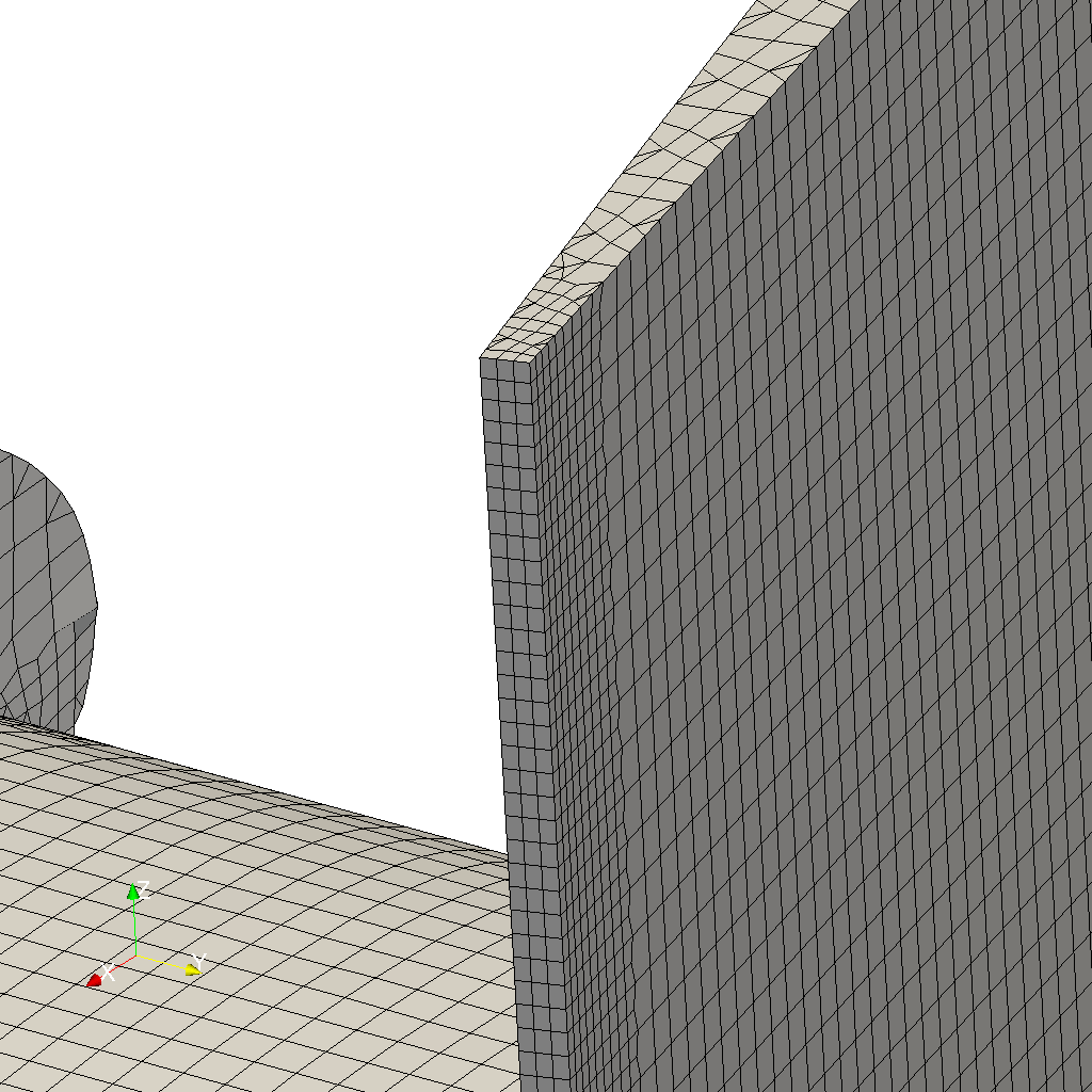
Note that no boundary layers have been added, because a set of closely controlled/monitored cell optimisation parameters is required to smooth out those cells. But the main reason it is not done on this particular wing is because there are 800k surface cells, on which if 20 boundary layers are grown, my laptop will not have enough RAM to even visualise the volume mesh ( need at least 10G of RAM to load it ).

But I do have a smaller mesh ( a wheel ) in which 20 boundary layers were added:

whose checkMesh returns:

Checking geometry...
    Overall domain bounding box (-10 0 0.389722) (40 6 8.4)
    Mesh (non-empty, non-wedge) directions (1 1 1)
    Mesh (non-empty) directions (1 1 1)
    Boundary openness (3.78916e-19 3.78831e-16 -4.22083e-16) OK.
    Max cell openness = 3.48028e-15 OK.
    Max aspect ratio = 127.821 OK.
    Minimum face area = 1.01365e-09. Maximum face area = 1.1977.  Face area magnitudes OK.
    Min volume = 3.18048e-12. Max volume = 1.33059.  Total volume = 2399.94.  Cell volumes OK.
    Mesh non-orthogonality Max: 73.3458 average: 7.22503
   *Number of severely non-orthogonal (> 70 degrees) faces: 100.
    Non-orthogonality check OK.
  <<Writing 100 non-orthogonal faces to set nonOrthoFaces
    Face pyramids OK.
    Max skewness = 2.90826 OK.
    Coupled point location match (average 0) OK.

Mesh OK.

As you can see, a set of clean stl files give you a good surface mesh and from there you may obtain a good boundary layer too.

I just spot another problem with the coarse mesh run. The absolute tolerance for the velocity fields are not small enough and Ux is no longer solved for the last few iterations:

Time = 500
DILUPBiCG: Solving for Ux, Initial residual = 6.50226222661e-06, Final residual = 6.50226222661e-06, No Iterations 0
DILUPBiCG: Solving for Uy, Initial residual = 1.93712216115e-05, Final residual = 4.70660878179e-06, No Iterations 1
DILUPBiCG: Solving for Uz, Initial residual = 1.37544730886e-05, Final residual = 8.88866037304e-06, No Iterations 1
GAMG: Solving for p, Initial residual = 4.4842154963e-05, Final residual = 8.93812980345e-07, No Iterations 4
GAMG: Solving for p, Initial residual = 4.94288599942e-06, Final residual = 8.29047562769e-07, No Iterations 1
GAMG: Solving for p, Initial residual = 1.09243422113e-06, Final residual = 5.23396505342e-07, No Iterations 1
time step continuity errors : sum local = 9.79919233392e-07, global = 2.4500148777e-08, cumulative = -0.00196944950993
DILUPBiCG: Solving for omega, Initial residual = 9.4735963376e-06, Final residual = 9.4735963376e-06, No Iterations 0
DILUPBiCG: Solving for k, Initial residual = 9.80221724403e-06, Final residual = 9.80221724403e-06, No Iterations 0
ExecutionTime = 1006.11 s ClockTime = 1014 s

The turbulence parameters k and omega are not either.
A reduced tolerance is desired.

@dylan - awesome images, thanks for sharing. What tools did you use for the actual meshing? snappy? A couple of points:

  • There is no difference in the feature set for community and professional plan, so everybody has access to all simulation features here on SimScale
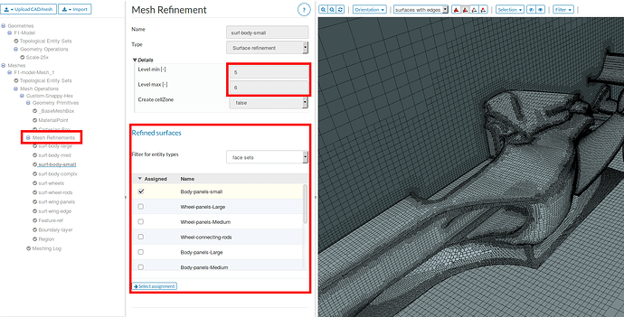
  • Local refinements based on specific surfaces is possible with SimScale, check out the screenshot below. You can address all surfaces of a model with a desired refinement level and also add region/primitive based refinements

  • “Splitting of geometry”: Generally the SimScale workflow is designed open, which means whatever you prefer doing locally / with your own tools you should be able to do it locally. So you could do splitting locally and then upload the splitted STL - SimScale will recognize each surface and you can assign mesh refinements onto them

  • Working with NURBS models: Agreed - let the CAD system do, what it can do best. So if you’re working in a BREP modeler, you can also upload the STEP model such that SimScale will take care of the tessellation if necessary.

Hope that helps.

@dylan - forgot to mention: keep the feedback coming, we’re eager to improve the workflow!

Hi,

Thank you for those images. I didn’t notice those features.

Now about my unstructured meshes. I am using both SnappyHex and cfMesh, the latter being another open-source mesh generator for OpenFOAM. The wing was created in SnappyHex and the wheel with boundary layers cfMesh. They both provide cut cells and are easy to implement. However, cfMesh has been a lot faster and more efficient for me despite less control entries in its mesh dictionary. SnappyHex allows for more parameter tuning in the mesh dictionary and some of those features are very useful in complicated cases.

Sorry the images of the wing were also from cfMesh, but I do have the same wing meshed by SnappyHex and was equally good.

Hi,

About the geometry split, a GUI environment is easy to be made a meshing Swiss knife. There are a brunch of STL manipulation utilities in OpenFOAM. One can use surfaceAutoPath name.stl newName.stl [angle] to split one large STL file into multiple parts within the same file. From there, executing surfaceSplitByPatch newName.stl will turn the one large file into multiple STL files, each containing one patch as split before. Now, with the GUI environment, one can go ahead and rename, delete, or combine those STL files. Finally, it is not hard and useful to combine all the patches into one STL file that contains all the individual names by using cat name* > newerName.stl.

Now, the amount of new patches generated by surfaceAutoPatch can range from 2 to 20000, depending on what angle is chosen and how clean the surface mesh is. With a dirty STL file, which is almost always the case, one will easily end up dealing with a few thousands of STL patches. This is where a GUI environment is highly appreciated, as it allows visual/manual interactions.

The above is only a small section of the surface mesh utilities that come with the OpenFOAM release but can potentially provide significant improvement in meshing efficiency, and reduced CAD usage.

The wheel mesh I uploaded was purely done with the STL manipulation utilities mentioned above in a TUI environment/Paraview, as there are only a few patches/shared edges that need to be recognised by the mesh generator.

@dylan - yes, these OpenFOAM manipulation utils are indeed neat. However most of the users here prefer to work with the actual NURBS model (e.g. STEP, IGES) where surface-splitting and merging is not relevant. By definition you can address the entire topology of those models, also during snappyHexMesh setup. But it seems that you prefer to work with the faceted model. Is there a specific reason for this? Do you want to have full control over the surface tessellation?

Hi,

I havent used stp/iges here and didn’t think I saw any public projects done that way. Could you please link me to one example as such? I would like to see how local refinements are applied when meshing with stp/iges.

There are two reasons I would like to split a geometry. Firstly, it is possible to capture all the important edges as all the patches and their shared boundaries are stored in the combined surface mesh file. Secondly, working with different patches is useful when saving computation power is desired as I gain full control over local cell size. If the same goals can be achieved with stp/iges through different meshing approaches, then why not.

Hi @dylan: Thanks a lot for the great and helpful guidelines. Concerning the *.step format, you may use the follwoing file:

Hi all,

I can see what you mean. Working with stp/iges is indeed very easy. If I would like to group those face entities

and rename them so that I get to work with less of them, how do I do that?

Thanks

One of the reasons I would like to work with face entities directly is I won’t need any refinement boxes. For example, if it is desired to reduce the cell size on and around a multi-element rear wing, I can assign a larger refinement level directly on the surface and ensure this refinement is extended for a certain distance away from the wing. Now, if I realise the wing is too high and wide, I can move the wing without moving any refinement boxes as there is none to start with.

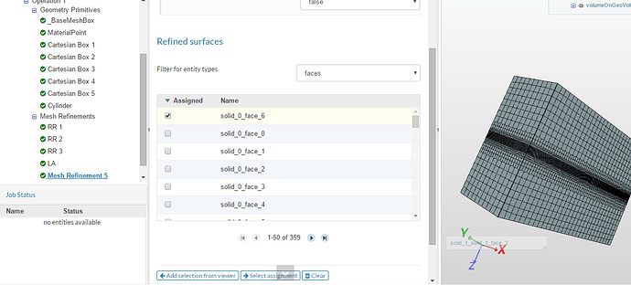
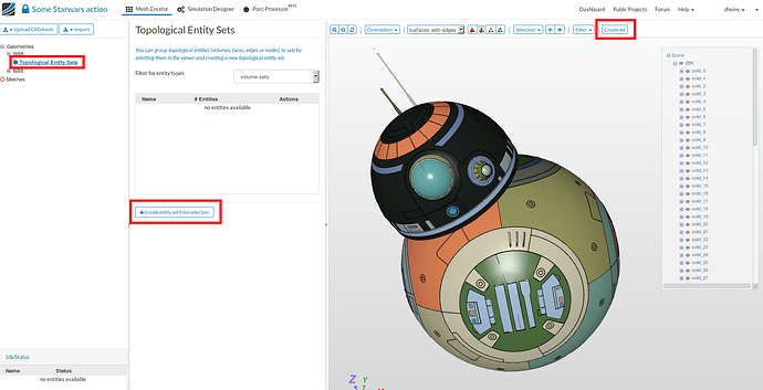
@dylan - valid point! Regarding the grouping of entities: This is done via the “Topological entity sets”. Each geometry or mesh has this points as a sub item in the tree. You click the faces together (or also use the invert selection option) and once you have the specific set selected, you hit the “Create set” button which then creates the new set that you will have available for assignment purposes in all mesh refinements or boundary conditions later on. See screenshot below

Side note: Star Wars ftw :smile: - Model from @pthomas over here: SimScale

2 Likes

I downloaded the single car STL file and tried splitting it locally. The output file ended up with 8000+ patches. Now I am going to switch to working directly with stp/iges. :grin:

Dear all (@dylan & @dheiny ),
I checked out the mesh log of the fine grid. The last lines are as follow:

Checking faces in error :
non-orthogonality > 65 degrees : 55
faces with face pyramid volume < 1e-13 : 30
faces with concavity > 80 degrees : 11
faces with skewness > 4 (internal) or 20 (boundary) : 2
faces with interpolation weights (0…1) < 0.02 : 1
faces with volume ratio of neighbour cells < 0.01 : 0
faces with face twist < 0.01 : 132
faces on cells with determinant < 0.001 : 11
Finished meshing with 242 illegal faces (concave, zero area or negative cell pyramid volume)


But for the coarse grid:
Checking faces in error :
non-orthogonality > 65 degrees : 0
faces with face pyramid volume < 1e-13 : 1
faces with concavity > 80 degrees : 4
faces with skewness > 4 (internal) or 20 (boundary) : 0
faces with interpolation weights (0…1) < 0.02 : 0
faces with volume ratio of neighbour cells < 0.01 : 0
faces with face twist < 0.01 : 26
faces on cells with determinant < 0.001 : 0
Finished meshing with 31 illegal faces (concave, zero area or negative cell pyramid volume)


Thanks to mention and highlight this issue which was the main problem. But I do not know what I have done wrong during the grid generation that resulted in such errors. In fact I could not split the *.stl file as a result of the high-resolution. So, I could only make region refinement.

@dylan: This is great to know that you are performing your PhD research on the aero-acoustics of a wheel. I always think how to simulate the flow around a wheel rolling over the ground. My question is how to deal with the singular point of the wheel-ground intersection (contact line). There should be a singularity as the velocities of the ground and the wheel at the contact line are different because the surface of the wheel which is in contact with the ground is flattened and we simply cut that part of the wheel. Such a singularity is also involved in the simulation of a droplet sliding over an inclined surface.

So, do you make a special consideration to overcome this issue?

Another question is that if the rotating zone in MRF can cut the boundary of the domain.
(@dheiny )

Hi

I have created a LMP with a stp file I found on Perrinn’s website during his workshop.

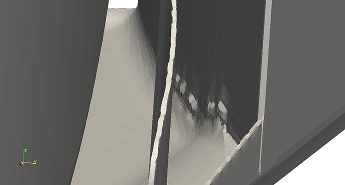
You can visualise zero-volume cells in paraview offline.


They are marked as red cells.

On a side note: I imagine you need about 50~100million cells to mesh the whole car properly when it is travelling at 70m/s, if you wish to control y+ within 30~50.

There are a variety of ways to simplify the contact patch. You can either cut a bit off the wheel, or cut it off and extrude the cut back to the original diameter creating near orthogonal corners. Diasinos has studied some effects of these simplications. The paper is part of one of the chapters in his PhD thesis.

It is difficult to maintain cell quality without the extra extrusion, but skew/non-orthogonal cells are less of an issue when located in low-gradient regions. The problem is, however, contact patches are where you see very large pressure/velocity gradients. It is important to obtain accurate results from a good mesh, although simplifications have to be made.

Wow, thanks a lot. The paper is great!