
Test, validate, and optimize your valve designs faster than ever before with SimScale’s powerful CFD, heat transfer, and FEA capabilities – all in the cloud.
Test, validate, and optimize your valve designs through CFD, heat transfer, and FEA.
The valve industry thrives on innovation and speed. Valve designers are tasked with creating custom designs and rapidly prototype in response to time-sensitive RFQs.
SimScale’s 100% cloud-based CAE software empowers you to accelerate design, eliminate prototypes, and optimize valve performance digitally.
Achieve superior efficiency, durability, and cost savings to boost your bottom line and bring better valves to market faster.
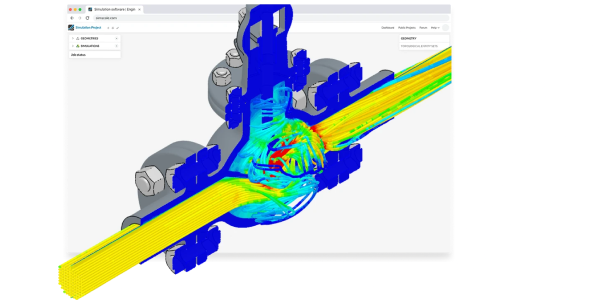
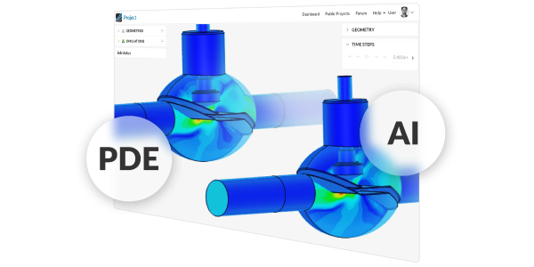
Revolutionize your workflow with SimScale’s AI-powered, cloud-native simulation. Our predictive AI delivers accurate, lightning-fast models in seconds, allowing you to explore more design variations, optimize flow control with precision, and accelerate innovation to bring superior valves to market with unprecedented speed, staying ahead of the curve.
SimScale empowers you to overcome common valve design hurdles and achieve superior performance.
Maximize throughput and efficiency, especially in space-constrained applications. Design the smallest possible valve without compromising volume.
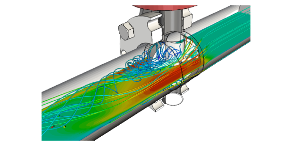
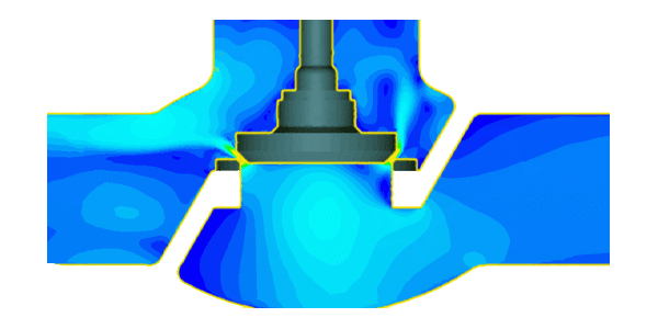
Identify and eliminate flow path inefficiencies that lead to energy loss. Visualize flow behavior to pinpoint problematic areas and achieve significant pressure drop reductions.
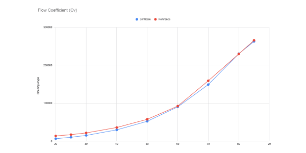
Select the perfect valve sizing for any application. Simulate multiple opening/closing positions simultaneously to automatically plot full valve performance curves in minutes.
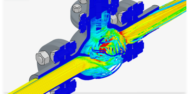
Prevent damaging pressure waves and ensure system stability. Understand how fluid motion changes suddenly and design valves to mitigate this critical risk.
Improve valve effectiveness and prevent costly failures. Pinpoint and address flow regions with high cavitation risk to optimize valve lifespan and performance.
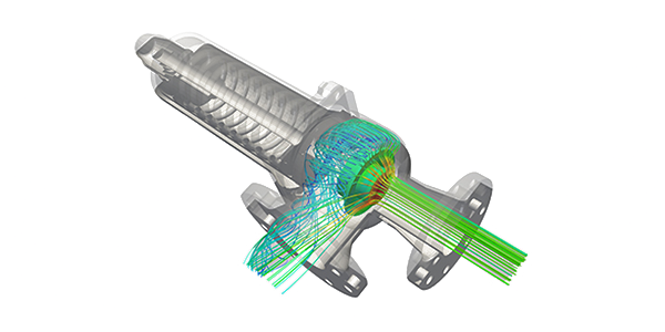

Ensure smooth, uninterrupted gas flow. Perform fluid dynamic analysis to prevent flow velocity from matching the speed of sound, avoiding system blockages.
Achieve the ideal balance of material efficiency and structural integrity. Identify high and low stress concentrations to inform smarter, lighter designs that withstand internal pressure and thermal loads

Customer Success
Using SimScale online CFD platform, Metraflex significantly optimized the design of their 4-inch check valve, and they have been using SimScale ever sicne.
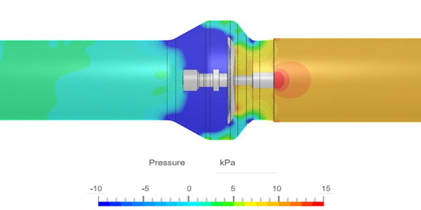


Check out all the success stories of our customers in the valve industry
See All StoriesCheck out the latest valve simulations performed in SimScale and validated against experimental and/or analytical results.
Your hub for everything about valve simulation and the world of analysis in the cloud.
Sign up for SimScale
and start simulating now