Error
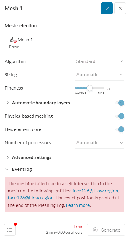
The meshing failed due to a self intersection in the mesh on the following entities: {entities}. The exact position is printed at the end of the Meshing Log.
What Happened?
The meshing process failed because there is one or more intersections in the model.
What Could Be the Possible Reason?
A self intersection in the mesh means that there are at least two mesh faces that are going through each other. The surfaces that are intersecting are displayed in the error message as observed in Figure 1:
Self intersections may happen due to insufficient surface mesh fineness near curved edges or other regions with complex topology.
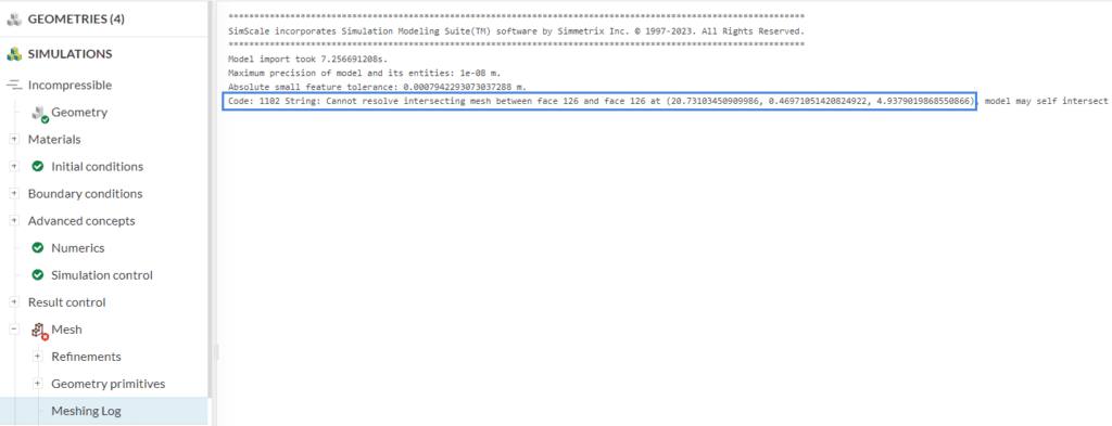
The exact coordinates of the intersection are at the end of the Meshing log, which is valuable for troubleshooting. You can access the meshing log in the simulation tree of your project.
What Can I Do Now?
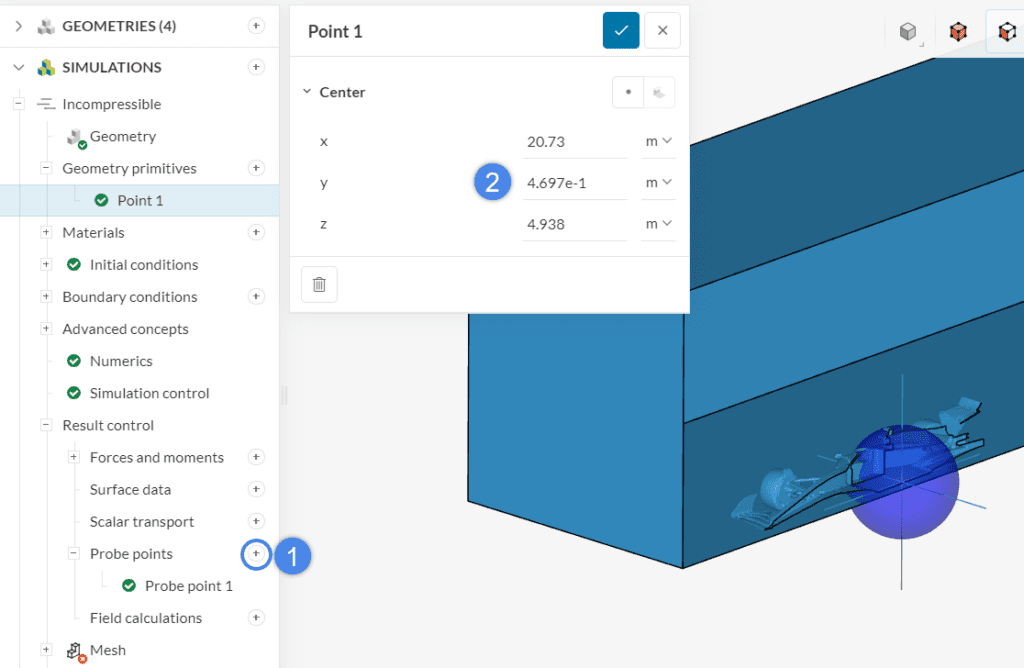
As a first step, creating a point geometry primitive (for example, via a probe point result control) with the coordinate shown in the meshing log allows you to pinpoint where the issue took place. By clicking on the faces shown in the error message, you can also highlight them in the viewer.
Mesh self intersections are commonly caused by insufficient mesh fineness around curved edges. After creating a probe point, carefully inspect the regions close to it, looking for potential CAD issues (small faces/gaps, highly curved faces, detailed topology).
The best approach may vary for different CAD models. However, after inspecting the region around the point primitive and spotting potentially problematic regions in the CAD, typical ways to solve the self intersection are:
- Cleaning up the CAD model around the problematic region
- Adding mesh refinements to the problematic region, aiming to better capture the detailed topology
- Increasing the small feature suppression, looking to suppress small CAD details
- In case you are using geometry in the stl format, exporting the geometry in a different format can help in some cases
Example
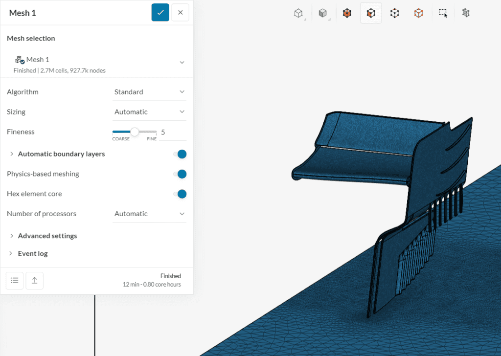
For example, the picture below shows a spoiler that can highlight how two mesh entities can intersect. After failing to generate a mesh due to a self intersection, the coordinates at the end of the meshing log are used to create a point primitive:
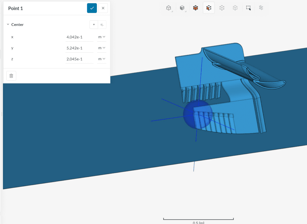
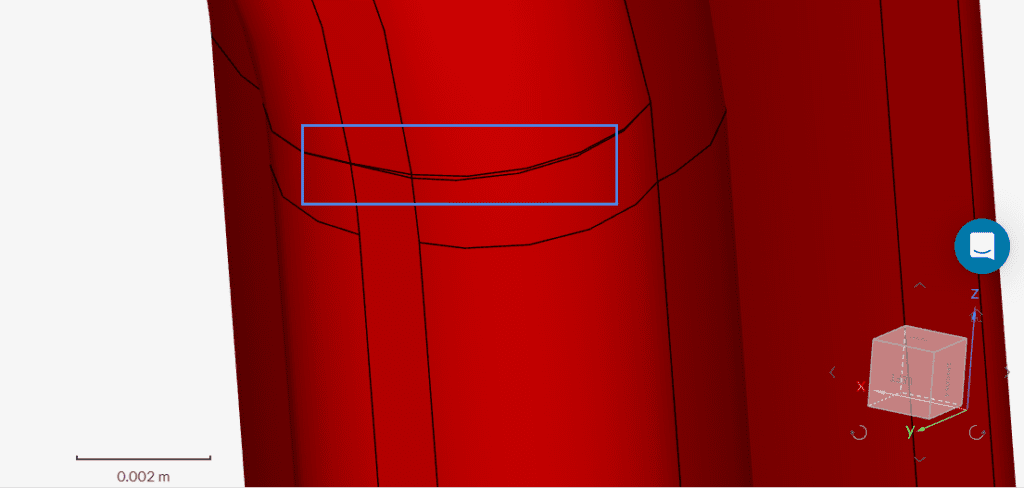
Inspecting the CAD model around the point, it is possible to find very thin faces next to the point primitive:
Such small and complex entities may cause the mesh to generate self intersections. The best approaches in this particular case are to increase the small feature suppression to a value above 50 microns (to suppress the highlighted features) or clean up the CAD model, removing the small entities from the spoiler.
With the appropriate changes, a successful meshing operation can be obtained.
Read more about how you can prepare your CAD model for SimScale here.
Important Information
If none of the above suggestions solved your problem, then please post the issue on our forum or contact us.
