SimScale provides multiple options for defining thermal conditions on a surface. This article outlines the available settings to accurately define thermal wall conditions. However, it does not cover radiative effects. For information on radiative walls, please refer to the dedicated article here.
Approach
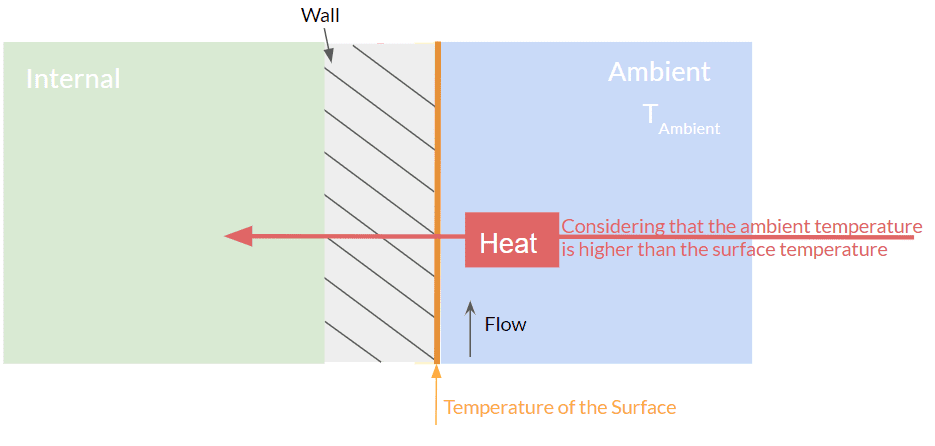
The schematic below illustrates the thermal conditions at a wall. Heat transfer occurs between the wall and the environment depending on the temperature difference and the flow conditions at the wall, either moving into or out of the surface.
How to set up the conditions depends on the given parameters, meaning the known physical boundaries of the system.

If you are wondering about the first two options, have a look at how to make a choice for (U) velocity.
The next item ‘Temperature type‘ concerns the thermal settings. There are three options:
- External wall heat flux
- Fixed value
- Adiabatic
Strictly speaking, options 2 and 3 are not physically possible in real life, but they serve as useful simplifications that improve convergence and reduce computation time. In most cases, the resulting error is negligible.
Fixed Value
The option fixed value means that the surface will have a constant temperature during the whole simulation.
Adiabatic
You chose the option adiabatic if you want your wall to be adiabatic, which means that there will be no heat transfer through the wall or the temperature has a zero gradient. Hence this wall will be considered as a perfect insulator.
External Wall Heat Flux
You should choose one of these if you are interested in the heat transfer due to an initial temperature difference in your system, or how the thermal situation in your system will change due to a heat transport you define. The following figure shows what to choose in different situations:

A. Derived Heat Flux
With this option, you need to define the flow situation outside the wall by specifying the convective heat transfer coefficient. Additionally, you can enable Wall Thermal to introduce a virtual layer, where you can define its thickness and thermal conductivity. This virtual layer represents an insulating or conductive material attached to the wall, affecting the overall heat transfer.
Using a wall layer is particularly useful in cases where you need to account for additional thermal resistance, such as walls with insulation, coatings, or composite materials. It helps in simulating more realistic thermal behavior by capturing the impact of material properties on heat dissipation.

B. Fixed Heat Flux
Here, you define the heat flux based on the dimensions of the surface, the total amount of heat being transferred will be calculated.

C. Power Heat Source
You define the heat power and the initial temperature of the surface. Unlike option B (fixed heat flux), where the heat transfer depends on the surface area, option C (fixed power) ensures a constant heat input regardless of size. This makes it particularly useful for cases like electronic components, heaters, or other applications where a specific amount of energy is introduced into the system without being affected by surface dimensions.
Assigning multiple surfaces
If you select more than one surface as a power source, every surface will produce the specified heat.
In other words: If you create a Turbulent Heat Flux BC, you specify 5W there and you select three surfaces, each surface will produce 5W. We are not specifying the total heat produced by all the surfaces selected, but the heat produced by each one.
Note
If none of the above suggestions solved your problem, then please post the issue on our forum or contact us.