This article covers how to calculate additional results in FEA simulations. For example, SimScale is able to calculate additional results, such as heat fluxes for Thermomechanical simulations and do a statistical analysis of the results.
Please visit the documentation page to learn more about all the result control items in FEA.
Result Control
1. Solution Fields
The results saved by the solution fields section basically saves the result parameters of every cell in the mesh. However, you can only see these results after the simulation starts running.
The parameter type that can be seen depends on the analysis type. As an example, in heat transfer simulations, the default result parameter is only Temperature, but in static simulations, displacement, Cauchy stress, von Mises stress, and total strain parameters are the default parameters.
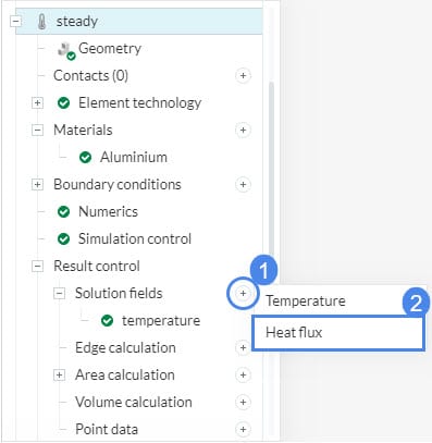
You will need to enable these additional calculations. As an example, you can save Heat Flux results in Heat Transfer Analysis.
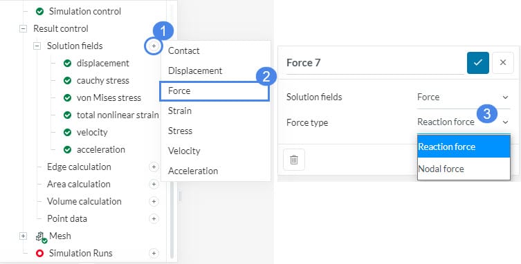
In structural dynamic simulations, you can enable additional calculations such as force parameter which has two variants: Nodal force and Reaction force. To include these calculations, you can follow the steps below:
- Click the ‘+’ symbol beside Solution fields.
- Select ‘Force’.
- Select the Force type that you want to calculate. You can choose between ‘Reaction force’ and ‘Nodal force’.
Nodal force vs Reaction force
Nodal forces are computed via integration of the internal stresses and strains over the element volume and express the force states on the mesh nodes.
Reaction forces at mesh nodes are computed from the nodal forces by subtracting the equivalent nodal values of external forces applied to the element. Reaction forces are key results of interest for any structural design, allowing for the evaluation of internal load paths and overall system response to applied loading.
To understand the difference let’s look at their behavior in given locations of the finite element model:
- On force application surfaces, nodal forces will equal the equivalent nodal values of externally applied force, whereas reaction forces will equal zero.
- On constrained surfaces (fixed or enforced motion) nodal reaction forces are the same as nodal forces.
- At internal points, in the absence of volume loads (body forces), both nodal and reaction forces should equal zero due to equilibrium within the model. When externally applied body forces are present, nodal forces equal the equivalent body forces whereas reaction forces equal zero.
2. Data Plots
Data plots visualize the result item as a time-dependent 2D plot and users can choose the result region as an area, volume, or as a point.
The calculation type should be chosen with respect to the result type.
Force Data
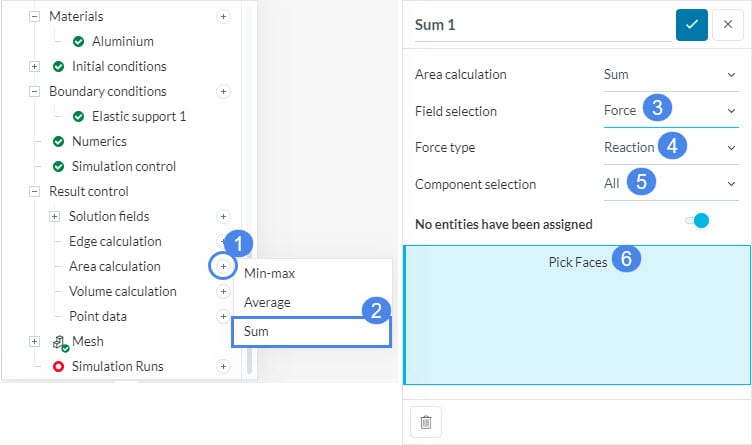
To calculate the reaction force on a selected surface the ‘Sum’ area calculation option must be used. This option sums up the nodal reaction forces on the assigned surfaces.
Pressure Data
If pressure data is selected, ‘Average’ or ‘Minimum and maximum’ would be the suitable area calculation type.
You can do this by following the steps below:
- Click the ‘+’ button besides Area calculation.
- Select the calculation of interest.
- Choose a Field selection. For example, we will calculate the reaction force.
- Select ‘Reaction’ as the Force type.
- Select in which direction will the force be calculated in Component selection. Here we will calculate force in all directions, therefore we select ‘All’.
- Assign the faces where the statistical analysis will be conducted.
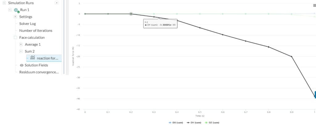
SimScale will update the plot while the simulation is running and you can see the final plot when the simulation is over. For example, the plot below is the plot of reaction force:
Note
If none of the above suggestions solved your problem, then please post the issue on our forum or contact us.


