NOTE: This tutorial was updated on 08/2016 to match the updated version of the platform
If you would like to watch the first session of the Drone Workshop again or in the case you missed it, you can access the full recording below.
You have just set up your [first simulation of the aerodynamics of a drone](https://www.simscale.com/forum/t/step-by-step-tutorial-homework-of-session-1-level-1/297) from the first session of our online Drone Workshop.Now we will start Level 2.
Level 2
Background:
Level 2 includes the CFD analysis of the modified ducted-fan geometry for the drone. This task requires you to firstly generate the mesh with a rotating zone and then setup a simulation with Multi-Reference-Frame (MRF) and advanced boundary conditions.
Step-by-Step instruction
Mesh
The CAD geometry is already provided in the Drone_HW-task-2 project, [that can be imported here]
-
Under the geometry tree, click on the geometry Drone_Ducted-Fan-STEP. From the geometry options panel, click on Mesh geometry. This will automatically create a Mesh operation and make the mesh operation selection panel active.
-
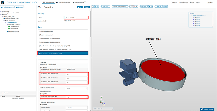
From the panel select > Hex-dominant parametric (only CDF). This type of meshing approach is necessary for the generation of a ‘rotating zone’ that is required for the analysis.
Important: The rotating zone is defined using an additional solid region included in the CAD geometry.
- In the same panel under Bounding Box Discretization specify the following values for number of cells in each X,Y and Z directions for the BaseMeshBox as shown in figure below:
- Number of cells in x direction: 40
- Number of cells in y direction :65
- Number of cells in z direction : 40
- and under ‘Parallel Processing’, the number of processors as : 32.
At the top, click on Save.
After saving , sub-trees named Geometry Primitives and Mesh Refinements will automatically appear under the default ‘Operation 1’ tree.
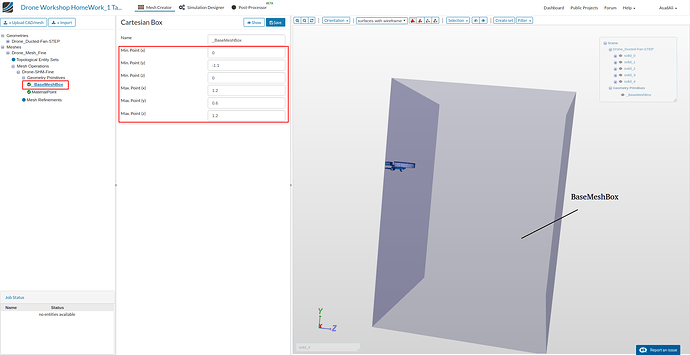
Under Geometry Primitives, click on BaseMeshBox and specify the values as shown below and click on ‘save’
Next, click on material point and specify the following sample values:
Center (x) : 0.113
Center (y) : 0.0677
Center (z) : 0.1731
This will place the material point in the space between the Bounding BaseMeshBox and the geometry surfaces. So, this is the confined space that will be meshed.
Next, create 3 additional geometry primitives by clicking on Geometry Primitives and then New from the options panel and select type cylinder. These will be used to define Region Refinements later on.
- Name the first as Cylinder-outer and specify the values shown in figure below and click ‘save’:
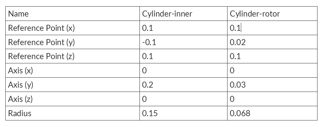
Similarly, for the other 2 geometry primitives of type cylinder specify the values given below:
Make sure you ‘save’ after each one.
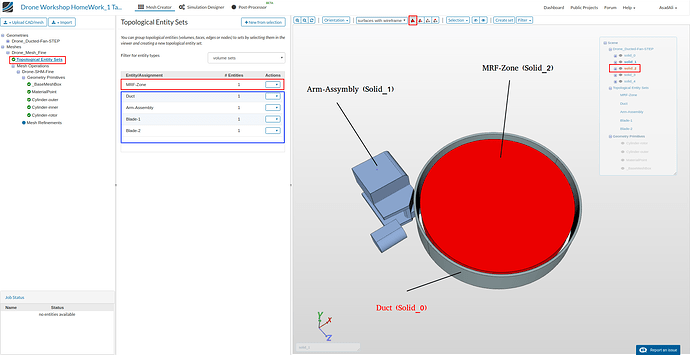
Now, we will group the geometry solids under the Topological Entity Sets tree.
First click on the pick volumes icon in in the tool bar above visualization window. Then select the MRF-zone and click on “Create entity set from viewer selection” in the options panel.
Onces created, hide the volume by selecting it again and clicking hide selection from the tool bar (slashed eye icon) so that only the rest of the volumes are visible.
Do the same for the 3 other volume sets. Once all volume sets are created, click on the show all icon in the tool bar (right to the hide selection icon).
Duct: Solid_0
Arm-assembly: Solid_1
MRF-Zone: Solid_2
Blade-1: Solid_3
Blade-2: Solid_4
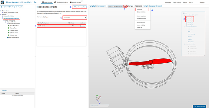
Next, from the visualization window selection tree, we will hide the Solid_0 till Solid_2 , by clicking off the eye symbols. Then, on the tool bar we click on icon pick faces, then click on selection and select all. This will select all visible faces of the rotor-blade. Lastly, click on Create entity set from viewer selection and name it blade-faces
Now, we add the necessary surface, region and layer refinements for the mesh.
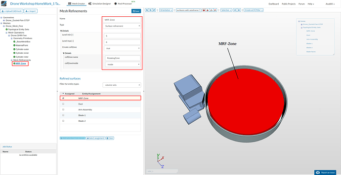
Click on Mesh refinements in the tree and add new mesh refinement from the options panel. Then select and enter the values as shown in the figure below.
Care must be taken that here for the type surface refinement , the create cell zone must be set to True and the volume set MRF-Zone must be assigned.
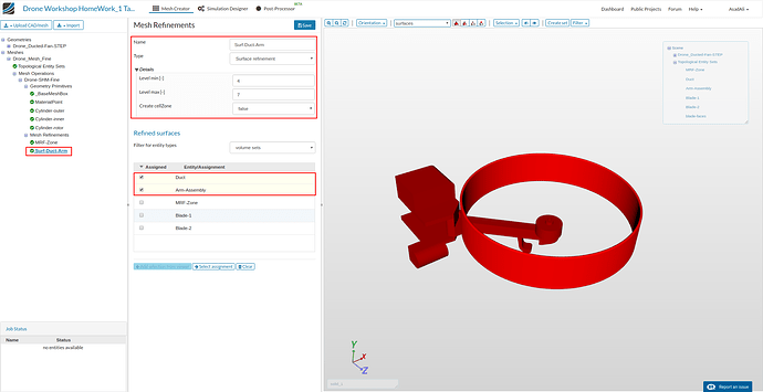
For refinement of the surface mesh of Arm-assembly and duct we add a new surface refinement and assign the values as shown in figure below:
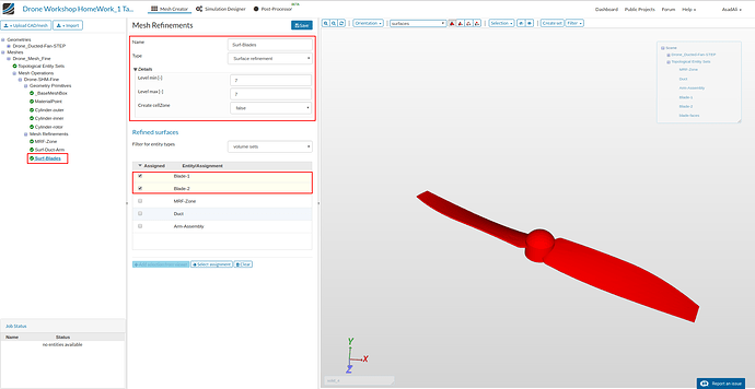
For refinement of blade surface mesh , we add another surface refinement as follows:
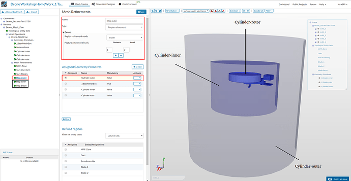
For refinement of the volume mesh region we add 3 region refinements of different refinement levels. So, click add refinements and add a region refinement as depicted below and save it.
Add 2 more region refinements with the specified values and save after each:
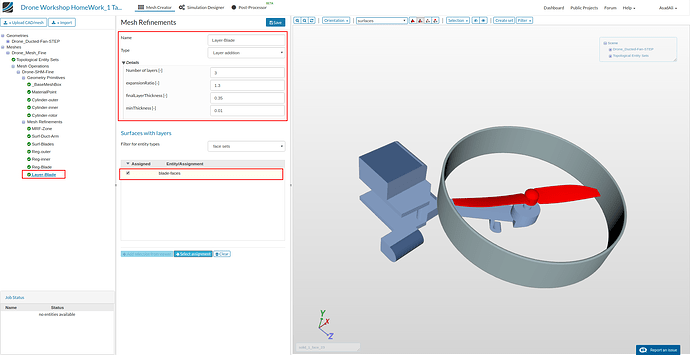
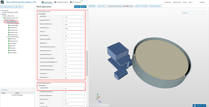
Lastly, we add body aligned cell layer to the rotor blade faces. So, create a new mesh refinement and select Layer addition with following values.
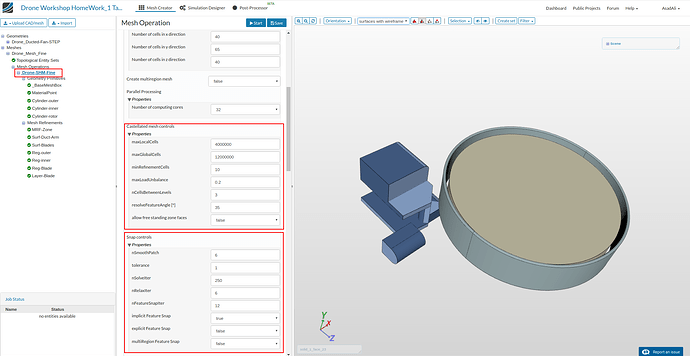
All the mesh refinements are now complete. We will now adjust some additional (advanced) settings to get a better quality mesh. So, make sure the corresponding values are as shown in the figures below:
Once done, click save and start the meshing process by clicking on the start button at top. The meshing process will take less than an hour to finish.
Simulation Setup
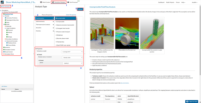
Switch to the Simulation Designer tab and select New Simulation. Enter preferred name and click create.
From analysis Type select the options as shown in the figure below and click ‘save’. After saving, a tree will automatically generate in the left panel window that will be completed step by step.
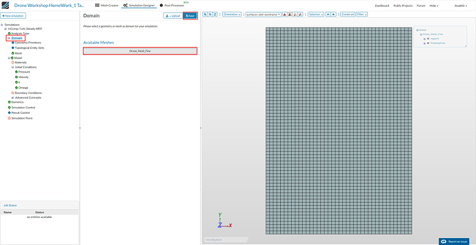
Next from the tree, click on Domain and select the mesh under Meshes and click Save as shown in figure below. After saving, the mesh will automatically load in the visualization window.
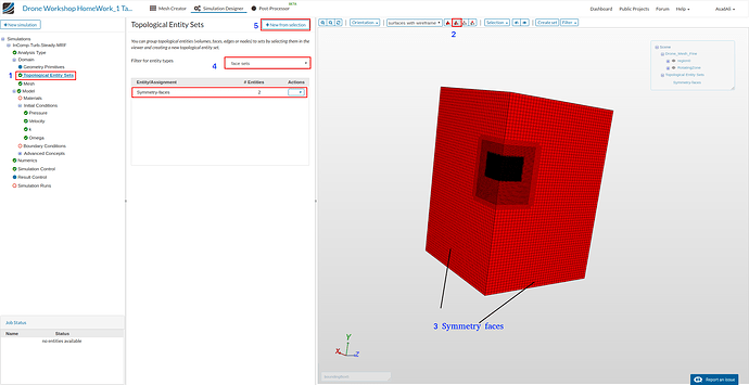
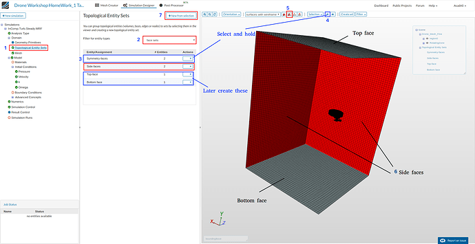
Now, we will create face sets under Topological Entity Sets that will be used to define boundary conditions later on.
Click on pick faces icon in tool bar [2] and select the highlighted faces [3] as shown in figure below. Change filter for entity types to face sets [4] and click on Create entity sets from viewer selection [5] to create the Symmetry-faces set.
Before creating the next set, we will hide the previous set Symmetry-faces by clicking on it [3] and clicking hide selection icon [4] to hide it.
Now, we select pick faces from tool bar [5] and select the highlighted side faces as shown in figure below [6] and click on Create entity sets from viewer selection [7] to create the sets called Side-faces.
Similarly, we follow the above steps to one by one create 2 new sets called Top-face and Bottom-face by selecting the corresponding faces shown in above figure.
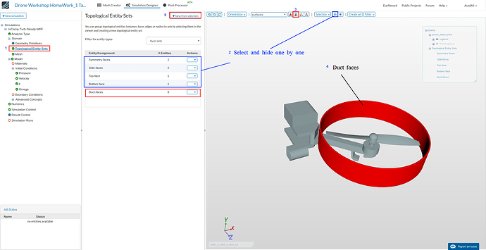
Onces done, we one-by-one hide the four face sets as shown in figure below [2] . Next, we select pick faces from tool bar [3] and select the highlighted Duct faces as shown [4] to create another set.
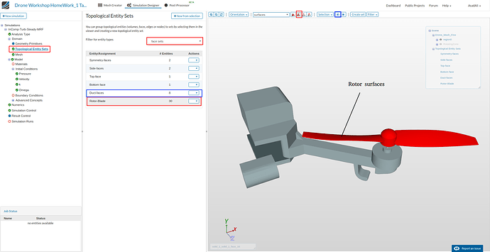
Again, we hide set Duct-faces first and then select all rotor faces (30 in total) to create a set called Rotor-Blade as shown below.
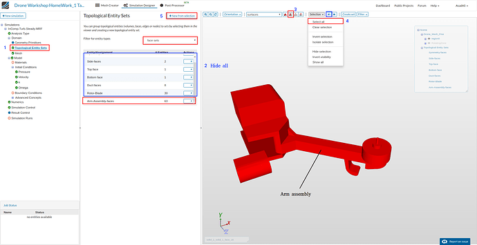
lastly, hide all created sets [2] and click pick faces from tool bar [3]. Now we see only the Arm-assembly in the viewer as shown in figure below. Click on selection in tool bar and Select all [4] to select all visible faces at once. So, create the last set called Arm-assembly-faces by clicking on create set button [5].
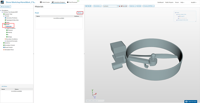
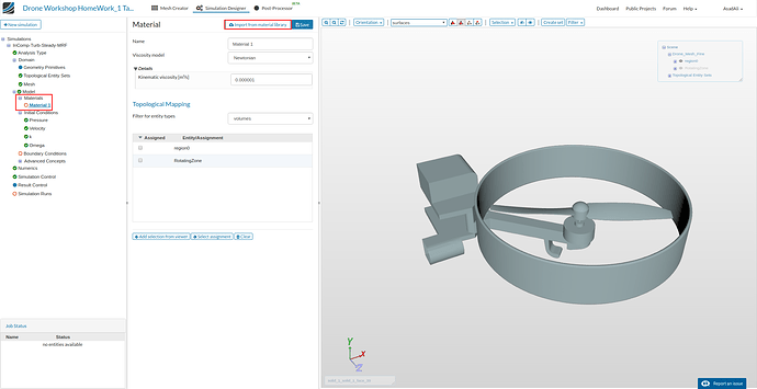
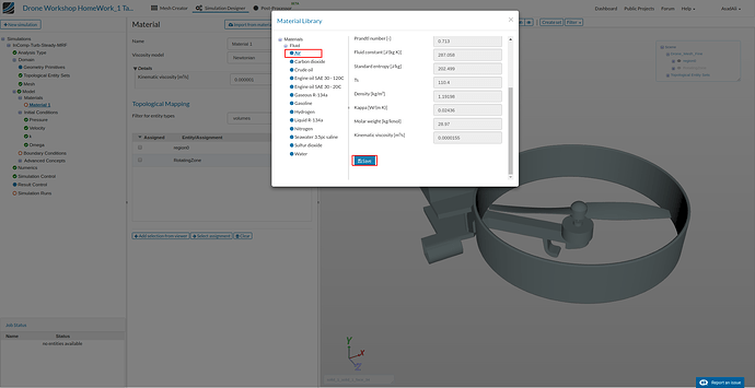
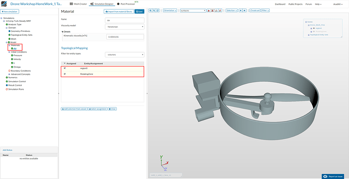
Adding Materials
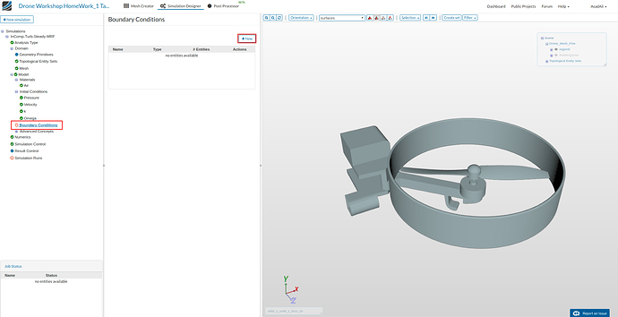
Now, we define the boundary conditions by clicking on the sub-tree named Boundary Conditions and clicking New from the options panel.
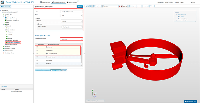
To define no-slip wall condition for the drone, enter and select the options as shown in figure below . Please note that you do NOT need to select from the viewer. Just assign by clicking the shown face set and click Save.
The second boundary condition is type symmetry and is setup as shown below. Again, just assign by clicking the shown face set and click Save (no selection from viewer required)
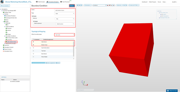
Similarly, we create a new Slip-wall condition for the Side/Bottom Faces as illustrated in figure below.
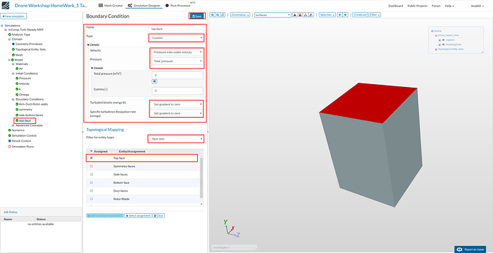
Lastly, we will make the top face an open boundary face that can act as a free flow inlet or outlet (at the same time) depending upon the flow inside the domain. To do third we choose type as Custom and set the values as shown in figure below:
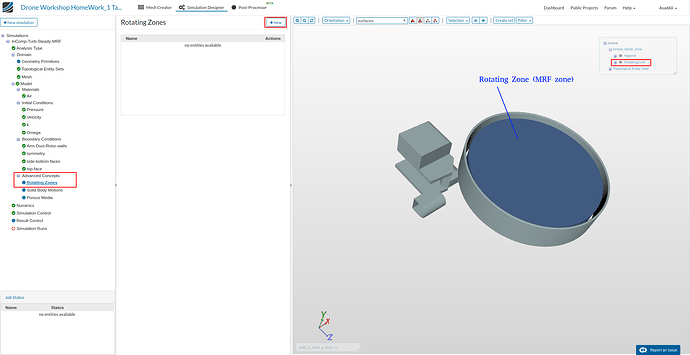
Now to define the rotation zone, click on Advanced Concepts sub-tree entry and Add rotating zone by clicking on the button in options panel as shown below.
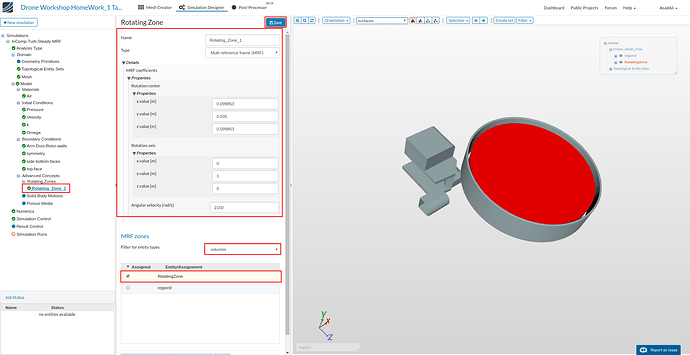
Select and assign the values as shown in the figure below to set the rotating MRF zone. Check RotatingZone under MRF Zone section for entity types volumes and click save
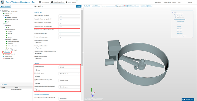
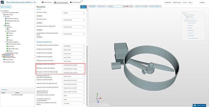
Under the Numerics sub-tree entry make the changes as shown in the figures below and save them.
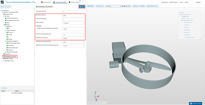
Make the following changes to the values as shown in figure below.
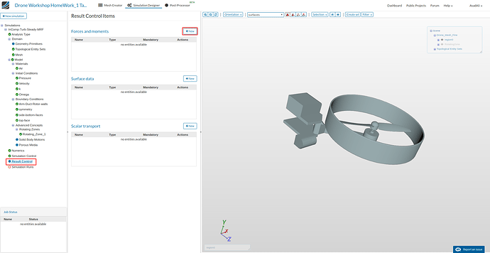
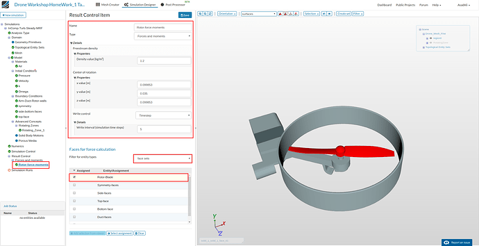
Click on Result Control and click New and add Forces and Moments item from the options panel and enter the values as shown in figures below. (Again, No selection from viewer is required).
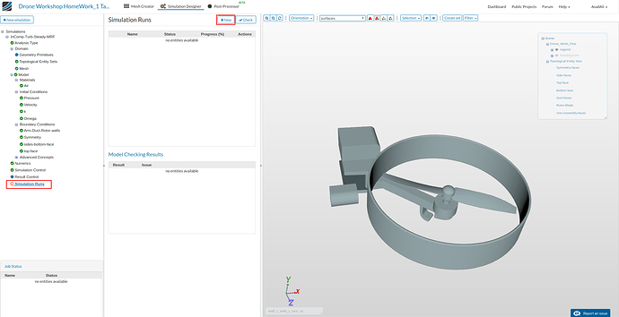
Finally, click on Simulation Runs, then on Create new run from the options panel as shown and start the run. Thats all … !
Congratulations, you have completed the Homework of Session 1 - Level 2 and can now move on to Session 2:
