Hi, I don’t understand why the velocity gave zero result despite I have set the boundary condition.
Hi @pkvoon!
Regarding the mesh I would also make sure to use inflated layers to capture gradient information. Could you explain why exactly you use the conditions you are using at the moment? Do you have reference values?
Just as an information: Prescribing the total pressure at the inlet allows you to get a fully developed profile in all pipe extension, which should (theoretically) match the pressure losses better than a velocity inlet.
As mentioned above and to avoid problems you need to satisfy y+ (Y-Plus) parameters in the near-wall region to use k-epsilon model appropriately.
Best,
Jousef
Hi @pkvoon,
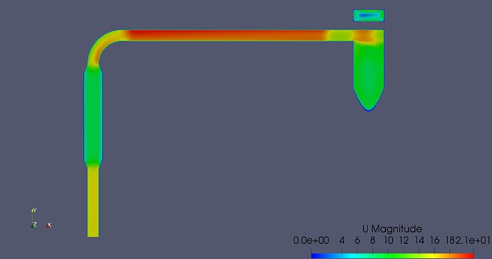
According to screenshot you see below where I have post-processed your latest run, there is a velocity gradient within the simulation. Is this what you were looking for?
Cheers.
Regards,
Barry
Hi @jousefm @Get_Barried , thank you for your input.
The function of this plant is to separate the palm oil nut and palm oil fiber.
For this simulation, we are trying to see the air flow across the system. The whole system is running at vacuum pressure. There will be a supply air fan operating at the outlet of the cyclone (D) to suck the fiber at the inlet (A). The fan outlet will be clean air. The fiber will be trapped in the cyclone (B). There will be an airlock at C. I hope my explaination is clear enough.
From our calculation, the fan will be operate at 16.1 m3/s. Fiber production is 3.06kg/s. Minimum fiber conveying velocity is 18.2m/s.
Yes, it is. But when I use clip filter, it shows blue colour (zero magnitude) only. May I know how do you get that result?
Hi @pkvoon,
I do my post-processing offline in ParaView so once you have that installed just download the results, load it into ParaView then set the time step to the final one before performing a slice filter through whichever direction you are interested in.
This video from SimScale will help you get started.
Cheers.
Regards,
Barry
