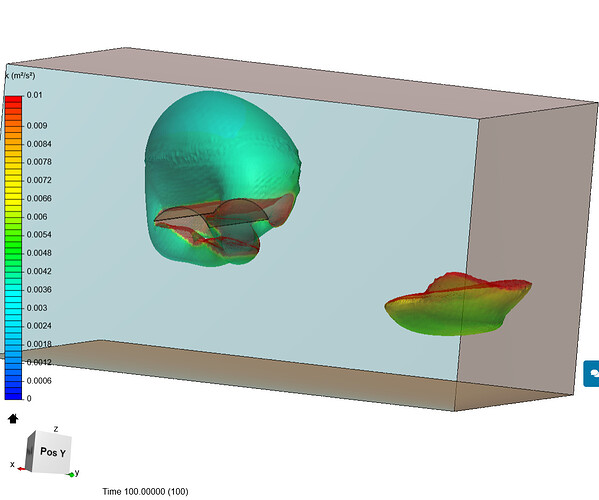
I am only interested in the output of the turbine currently. Unfortunately, the result is still not stable. I will try reupload the geometry now. Sigh
The rear BMB face then needs only to encompass the wake exiting the shield outlet.
After the first good sim run, you can check velocity vectors near the BMB walls to determine whether the geometry is affecting the air significantly near the wall, if so need to move that BMB face further away…
I would still make the BMB sides and inlet significantly further away.
Again this is very little # of cells and computation core hours cost for the increase of accuracy obtained. (Cells well spent  )
)
Ok , I tried increase the size of my mrf zone already , may I know, if that still doesnt solve the convergence problem, what else can i do?
All my other suggestions, starting back at Post 5 ![]()
Like I said, since you redo CAD anyway all my suggestions in this topic now come into play…
Ok sir, i really hope changing the mrf size will help, feeling so stressed and tired now 
That is why, if MRF is not the only culprit here you should try as many other suggestions in this topic as possible in your next sim try (none of which I believe will hinder convergence except maybe switching to TETforCFD mesh, but I present a solution for that here…
There will be more convergence suggestions if you have convergence issues, AFTER we think that you have the best geometry and best volume mesh we can achieve for your needs…
Accurate results from CADA are tedious to obtain ![]()
Check this topic out if you want to see real perseverance to got OK results…
Just so that you can convince me to agree more with your opinion…
Are you telling me that when the geometry would deflect some air particle, which is at quite a distance from the geometry, out of this Custom>Inlet-Outlet face (I sort-of view them as open windows) , that you can be sure the same particle of air will re-enter the window in the same place and at the same speed and direction as it would have been if that custom window was further away than its real path to begin with (I am assuming we are at a place where that particle would get sucked back in from low pressure generated downstream around the geometry)?
If that answer here is YES, I will use very small BMBs with out Custom BC from now on…
That is a mouthful but I hope you get the gist…
In 7 hours I can correct that (I hit some sort of edit limit ![]() )…
)…
To:
I will use very small BMBs with our Custom BC from now on
Hi @DaleKramer: I did not know there are any edit limits: hope it is solved for you…
From observation of small BMB (velocity vectors or particle traces) I see that those BC defined as Zero Gradient are ‘leaking’, so air or water will travel the BC in both directions. This is pressure-wise as kind of surface tension prevents complete fluid evacuation. In any case, most of fluid will still be evacuated by Pressure outlet.
As we do not have programme insight into Zero Gradient BC, this is just the ‘intuition’. May be somebody from inner circle will help to understand the real nature of Zero Gradient BC. 
Cheers,
Retsam
OK, but have you seen air getting ‘sucked’ back in?
I’ve seen iso surface or iso volume shaping in a way ‘coherent’ to space filled with that medium. I repeat that the space outside the BMB seems filled with medium and not being void. So it is implicit and subjective impression…
I think I will investigate by placing ZeroGradient walls close to an object such that it would send air out to bump into that ‘force’ field and consequentially, it would also would try to suck that force field inwards, downstream.
Then look at the velocity vectors from that ZeroGradient setup and compare them at the same location, from the same object, in a VERY large BMB with slip walls…
I think that would answer my question…
I cannot work today with Simscale: “Connection to server interrupted: Attempting to reconnect…” message is coming for a while, so I would not produce any example.  It may be also linked to Internet traffic here. So far, so bad.
Still having this issue Andrzej? For me everything works smoothly at the moment.
Cheers,
Jousef
@DaleKramer @Retsam @jousefm
My problem solved. It is solved by changing the MRF size. There must be some clearance between the MRF zone and the turbine’s blade.
It still persist with:
That project is now shared with support and Solution Field cannot be loaded in one of my simulation.
I did also the following:
- Cleaned the Chrom cache.
- Restarted SimScale
- Log off and on in SimScale
- Restart Internet connection.
Nasty, cycling every 3-6 seconds… ![]()
![]()
Retsam
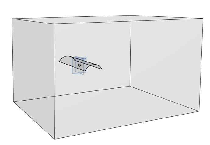
@DaleKramer: I have small example of Zero Gradient BC, making my tunnel in a project started two days ago in order to validate TET mesh for CFD. I’m also testing your ‘numerics’ which could save time and core-hours. But for the moment look at that:
Half-pipe shape (0.5 x 0.18) flies in a full TET BMB (1.5 x 1.0 x 0.87).
Front wind is of 10 m/s in X- direction.
Iso volume of velocity > 10.2 m/s
Tunnel is all Zero gradient, standard Velocity inlet, standard Pressure outlet.
Here is also perspective view of that device from OnShape:
Cheers,
Retsam
Looks like a good setup for investigation, can you send me a share on the project?


