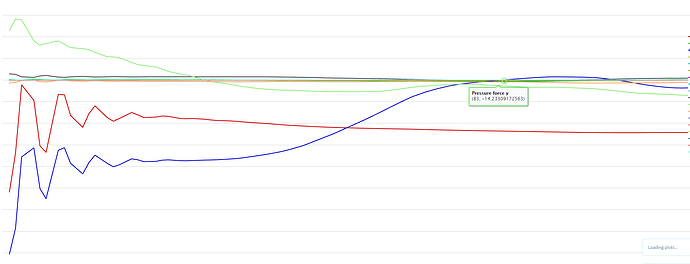
when i originally ran this basic design i achived a Cd of 0.2424, a very promising value and very close to the 0.21 that the car is claimed to achive but i wasnt satisfied with the mesh so i went away and redid it from scratch but now when i sim i get a drag value approximatly twice what is expected (793N) and i cant decern why, speed it was run at was 31m/s, (70mph) and the area was 2.37m according to paraviewer, this all in gives a very high Cd of 0.56, any idea how?
Hi @Lemlurker,
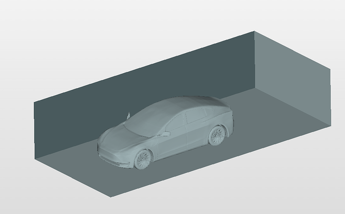
I just took a very brief look at your project (plan on digging deeper later) - the first thing that I noticed is that your computational domain is very small / its boundaries very close to the vehicle:
that way the result fields will interact with the inlet, the sides/top as well as the outlet which will skew the results. This is an image from @Maciek’s post:

Here you can see nicely that if you go along the boundaries of the domain, the velocity magnitude almost doesn’t change anymore. However if you would now shrink the domain closer to the vehicle like in your case, the boundaries would interact significantly with your results fields.
Long story short: I’d give the bounding box a couple of vehicle lengths upstream and downstream as well as sides and top.
Best,
David
this was the econd run, i had run a simulation with a much larger domain and ggot the same results, i ran it smaller because i couldnt see making it any bigger having an affect
Hi @Lemlurker,
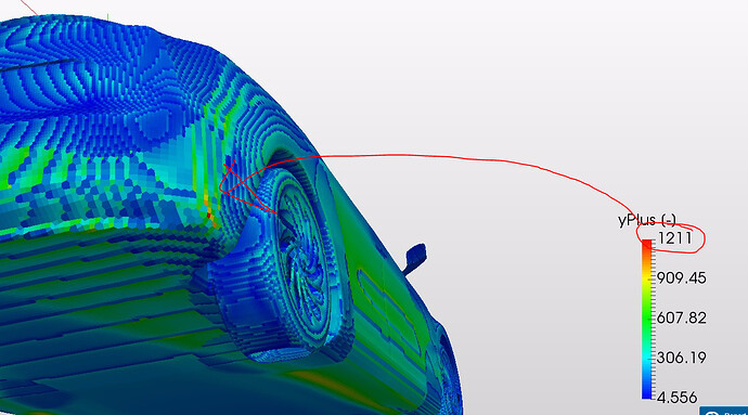
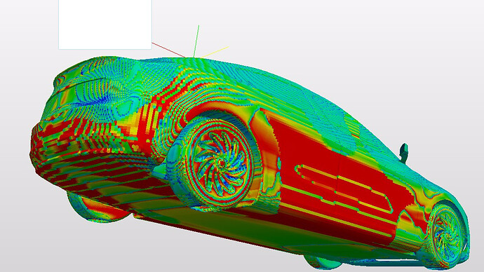
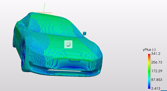
Just had another quick look on your project and my initial thought would be to monitor the yPlus in your result. You could add it as a result control item. This may be done as: Result Controls > Field Calculations > (Type) Turbulence> Dimensionless wall distance (y+).
Since you are using wall functions, the y+ need not be in the vicinity of 1 but should be within the range of 30 to 300. Values higher than this would result in unrealistic friction drag values, which may well be the case for your simulation.
Kindly let us know if this helps. Or if it doesn’t 
Best,
Krishna
this might be a bit of dejavu but im just back into this after a break at home over easter, i have input my latest mesh for my tesla and set it all up as usual but im getting a value for drag that is almost EXACTLY twice that of which i am expecting to get, going through the numbers: the drag value im getting is 580N, at a speed of 31 m/s (70mph), using a density of 1.225, and a calculated area of 2.36M^3 that gives us a top opf the fraction of 580 and bottom of 1412.455, 580/1412 gives us a cd of 0.41… this vehicles apparent Cd is rated at 0.21, for this project to proceed i need to get the cd to within 0.21 and 0.24 before we can begin experimentation ( the difference is to allow for minor surface defects in my modeling, i could understand a few Cd points out but almost exactly double? i cant really think of what i could have done to my mesh to make it go that AWOL lol, any help much apreciated
latest run was done at 50mph with the same (albeit sligtly lower) Cd value https://www.simscale.com/workbench/?pid=1649467118420600070#tab_2-0
any ideas? at the very lease any ideas to reduce surface turbulance? i really need to get the Cd down to realistic levels and im almost certain its not my mesh thats to blame
got Yplus down to acceptable levels by running in lamilar flow instead of turbulant, even more drag… grrrrr
Hi @Lemlurker, I looked at this last night. Which simulations am I looking at? I noticed all the ones I flicked through were not converged and the result control items were not steady?
Kind regards,
Darren
they tend to all time out but the drag output results look steady, especially in my latest oine run without any turbulance model was steady at 600N of drag, the one termed 70 mph turbulance reduction
I’ll copy your project and do a few runs.
Kind regards,
Darren
i also did notice on the last run that it was only 4 cores so it timed out unusually early but thanks for the hel, i should expect somewhere in the region of 200-300n of drag for the Cd value to match reality
@Lemlurker I would add layers to the mesh, define the walls as no-slip/wall function and add a turbulence model. I think you need to be looking at parametric meshing as you would have more control over refinement. Adding layer inflation and surface refinement to the car and leaving the rest of your mesh corse would save you a lot of core hours.
I think we need to start here to rule out issues from the mesh. And I know above you said that you tried making the mesh bounding box larger but I would recommend making it larger still a general rule someone once said to me was 5 times the dimension of the object in each direction and 15 times in the flow direction. If this doesn’t work at least we shall have a very good mesh to start.
Kind regards,
Darren
i started out running it with turbulance model and no slip vehicle walls lol, but ill definitly try somt of the other parts
Hey guys,
I’m dealing with kind of the same issue. I want to validate drag force of a sphere and with manual mesh I get twice the value I expect.
And as I was thinking about it, the memory popped my mind that a year before @AsadAli has solved a similar case for me. My bad, I haven’t really went through his solution to compare with my setup but I’ll do it and report my findings.
The thread can be found here:
My current project is here:
The funny thing, with very fine mesh I get exact values (approx. 10% error) but it took 84mins. The automatic mesh came with double drag force. But I also reduced the boundary box so maybe that is the thing in my case.
Anyway, I’ll investigate it and will come back to share what I found.
Have a nice day,
János
thanks for the info, ill take a look and give this a go
do ou have a link to the threead since it seems to be to your project instead
Sorry, this one:
