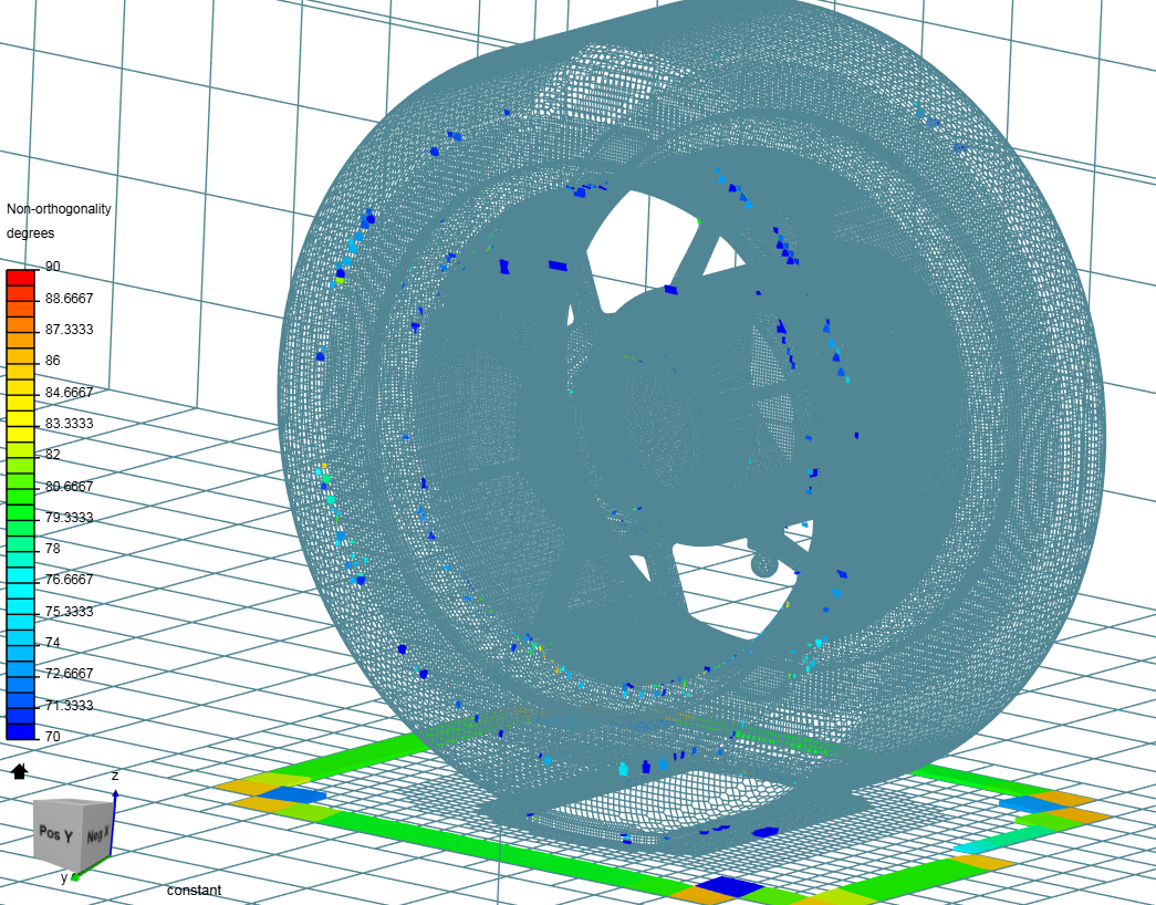
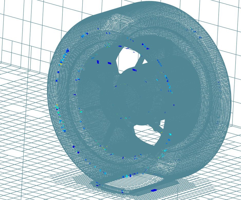
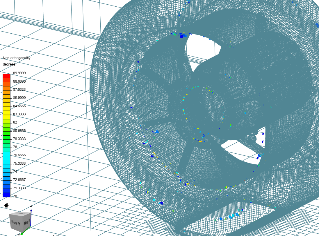
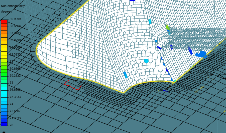
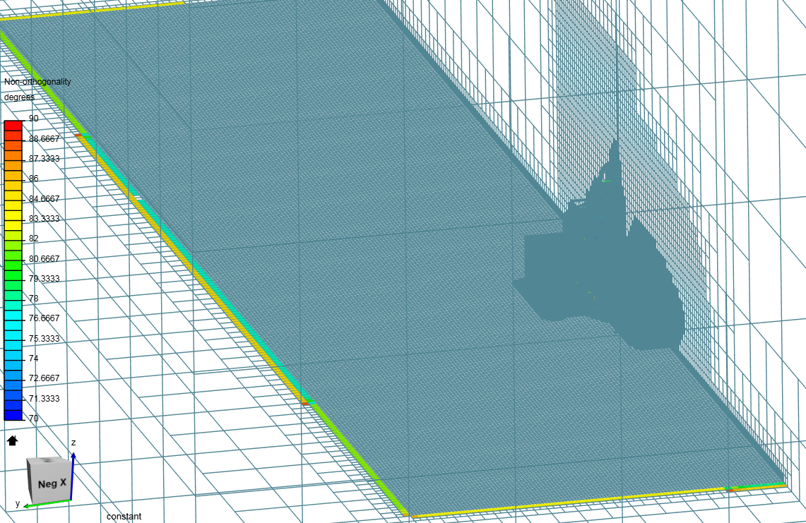
Based on the findings with the mesh quality feature, I have done a quick test to see how changes in CAD geometry and Mesh settings affect the total Non-orthogonal cell count.
PLEASE GIVE ME ADVICE AND GUIDANCE HERE. I WOULD LIKE TO UNDERSTAND THIS CONNECTION BETTER SO THAT I CAN GET BETTER MESHES QUICKER.
@DaleKramer @Ricardopg
Below is the full list of settings i used for the half car sim. I will track changes of the settings and also add pics of the solutions field results for each test.
Project LINK : HERE
Baseline test run from RH.31.15_Y.0.003_R.0_P.0_SA.0_S.16.5
Finished | 11.1M cells, 13.1M nodes
| Mesh | Half car and Wheel test 6 settings | Wheel test 6.1 settings | |
|---|---|---|---|
| Bounding box resolution | X | 28 | |
| Y | 7 | ||
| Z | 7 | ||
| Castellated Mesh Controls | Max local cells | 4e+7 | |
| Max global cells | 1e+8 | ||
| Min Cell refinement | 5 | ||
| Max load unbalance | 0.2 | ||
| Cells between levels | 1 | 2 | |
| Resolve feature angle | 30 | ||
| Snap Controls | Mesh to geometry conformation | 7 | 10 |
| Tolerance | 2 | ||
| Solver Iterations | 300 | ||
| Relax iterations | 8 | ||
| Max mex confirmation iteration | 10 | ||
| Implicit feature snap | ON | ||
| Explicit feature snap | OFF | ||
| Detect features between multiple surfaces | ON | ||
| Layer adding Controls | Layer size | OFF | |
| Max cancelled layers near sharp features | 0 | ||
| Feature angle | 180 | ||
| Slip feature angle | 75 | ||
| Relax iterations | 8 | ||
| Surface normals max smoothing iterations | 2 | ||
| Internal mesh max smoothing iterations | 5 | ||
| Max face thickness ratio | 0.5 | ||
| Max thickness to medial ratio | 0.3 | ||
| Min median axis angle | 90 | ||
| Buffer cells between refinement levels | 0 | ||
| Layer addition max iterations | 50 | ||
| Max iterations with strict quality controls | 20 | ||
| Mesh quality controls | Max non orthogonality | 75 deg | 65 |
| Max boundary skewness | 20 | ||
| Max internal skewness | 4 | ||
| Max concaveness | 80 | ||
| Min volume | -1e+30 | -1e+13 | |
| Min tet quality | -1e+30 | ||
| Min face area | -1 | ||
| Min face twist | 0.01 | ||
| Min determinat | 0.001 | ||
| Min face weight | 0.02 | ||
| Min volume ratio | 0.01 | ||
| Min triangle twist | -1 | ||
| Error distribution iterations | 4 | ||
| Error reduction | 0.75 | ||
| Relaxed max non orthogonality | 75 deg | 70 | |
| Merge tolerance | 1e-6 | ||
| Results | Total Illegal faces | 30 | |
| Lower is better | Volume Ratio | 127.3 | |
| Should be Less than 150 | Max Aspect Ratio | ? | |
| non-orthogonality > 75 degrees | 16 | ||
| faces with concavity > 80 degrees | 0 | ||
| faces with skewness > 4 (internal) or 20 (boundary) | 3 | ||
| faces with interpolation weights (0.1) < 0.02 | 1 | ||
| faces with volume ratio of neighbour cells < 0.01 | 1 | ||
| faces with face twist < 0.01 | 9 | ||
| faces on cells with determinant < 0.001 | 0 | ||
| Time to Mesh | 4026s |
Based off this information it seems that i need to reduce the Non-orthogonality to below 70°
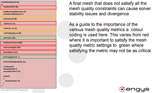
Research has also alerted me to best practices for a healthy mesh as said here
- high aspect ratio cells usually appear in very fine boundary layers. It is not fatal for the solver stability, but can significantly decrease convergence speed.
- non-orthogonality (nO) is a very important parameter, we can define three ranges of its values:
- nO < 70 - safe values
- 70 < nO < 90 - require special treatment of , e.g., nonOrthoCorrectors in fvSolution or numerical schemes in fvSchemes
- nO > 9O - bad mesh, which can not be used for simulation
- skewness - higher values may impair quality (accuracy) of the results, anyway any reasonably high value (<20) of skewness parameter can be used for simulation
TESTS
Wheel test 6
-
Mesh settings from Half car sim
-
Only level 4 active tunnel
Checking faces in error :
non-orthogonality > 75 degrees : 5
faces with concavity > 80 degrees : 0
faces with skewness > 4 (internal) or 20 (boundary) : 0
faces with interpolation weights (0…1) < 0.02 : 0
faces with volume ratio of neighbour cells < 0.01 : 1
faces with face twist < 0.01 : 1
faces on cells with determinant < 0.001 : 0
VolumeRatio
min: 1.0000000000444333
max: 111.13924675573229
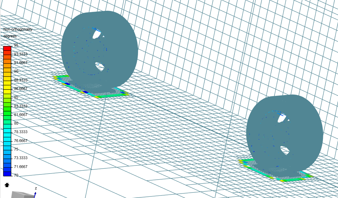
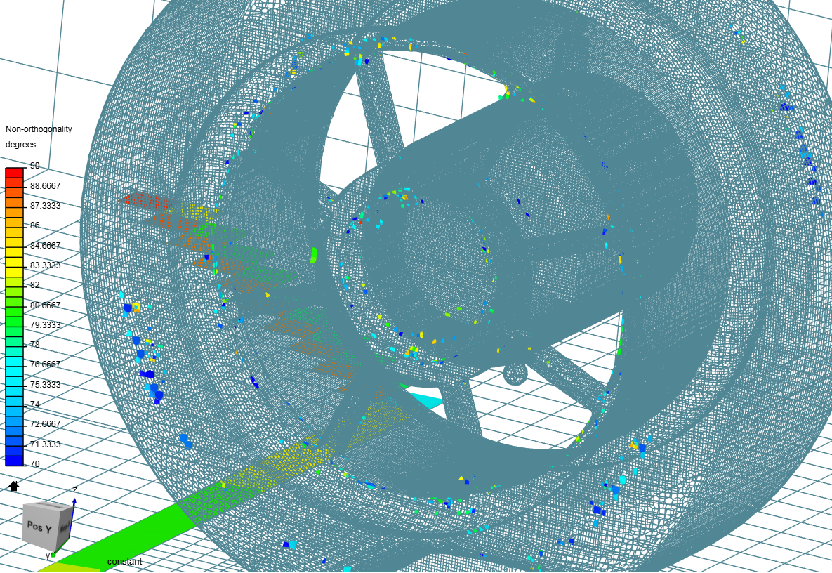
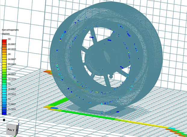
While there are only 5 non-orthogonal cells in this run, the Max Non-ortho was set to 75° which falls in the “not-so-good” zone of cells. The plan is to use the mesh quality feature to see where cells have Non-ortho over the 70° value, and concentrate in fixing these areas.
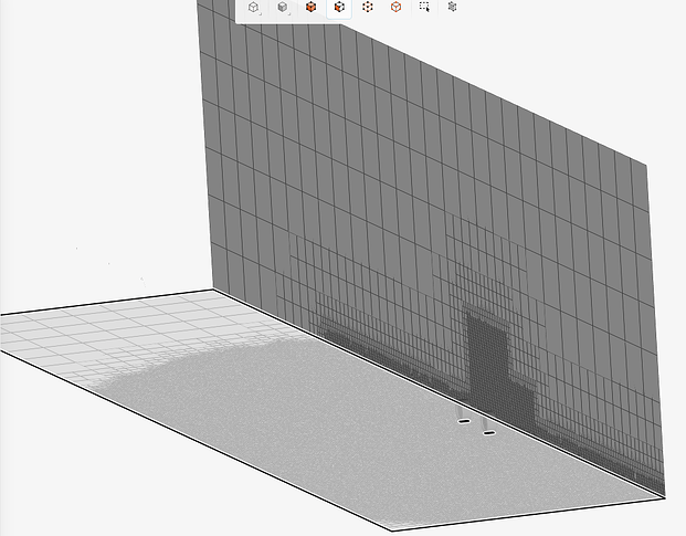
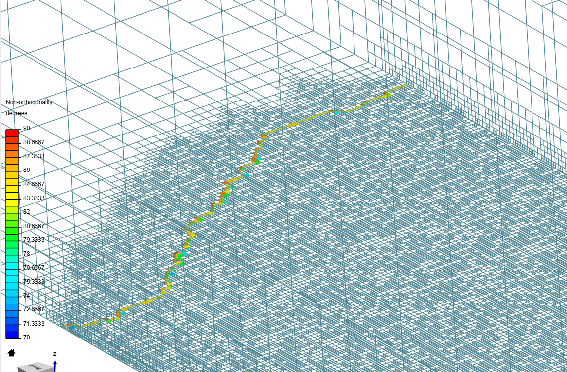
It seems that the Bounding box layer addition (BL on floor) is terminating when the cells become coarse towards the bounding box cell sizes. These cells here are the very ends of the Boundary layer connecting to the floor. I do not know how to fix this. I am not sure why the BBLA is deleting layers here.
NOTE test mesh 6.1 and 6.2 are both used with the Wheel test 6.1 geometry similar setup is also done in test 7 & 8
Wheel test 6.1
New mesh settings used
- Cells between levels - 2
- Max non-orthogonality - 65
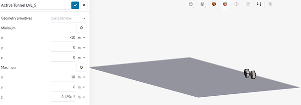
- Level 5 active tunnel used to increase cell fineness.
Checking faces in error :
non-orthogonality > 65 degrees : 2050
faces with face pyramid volume < 1e-13 : 0
faces with concavity > 80 degrees : 0
faces with skewness > 4 (internal) or 20 (boundary) : 0
faces with interpolation weights (0…1) < 0.02 : 41
faces with volume ratio of neighbour cells < 0.01 : 0
faces with face twist < 0.01 : 1
faces on cells with determinant < 0.001 : 3
volumeRatio
min: 1.0000000000168079
max: 258.62928332572926
The large increase in Non-ortho cells is due to changing the MAX non-ortho value to 65.
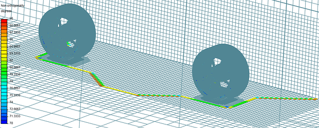
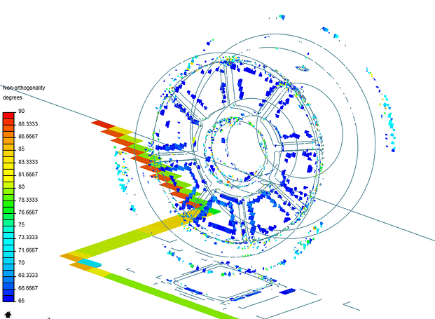
The increased level region refinement seems to have moved the Bounding box layer addition termination area to make this shape. It seems cell size does help but i think the layer adding settings could be the culprit.
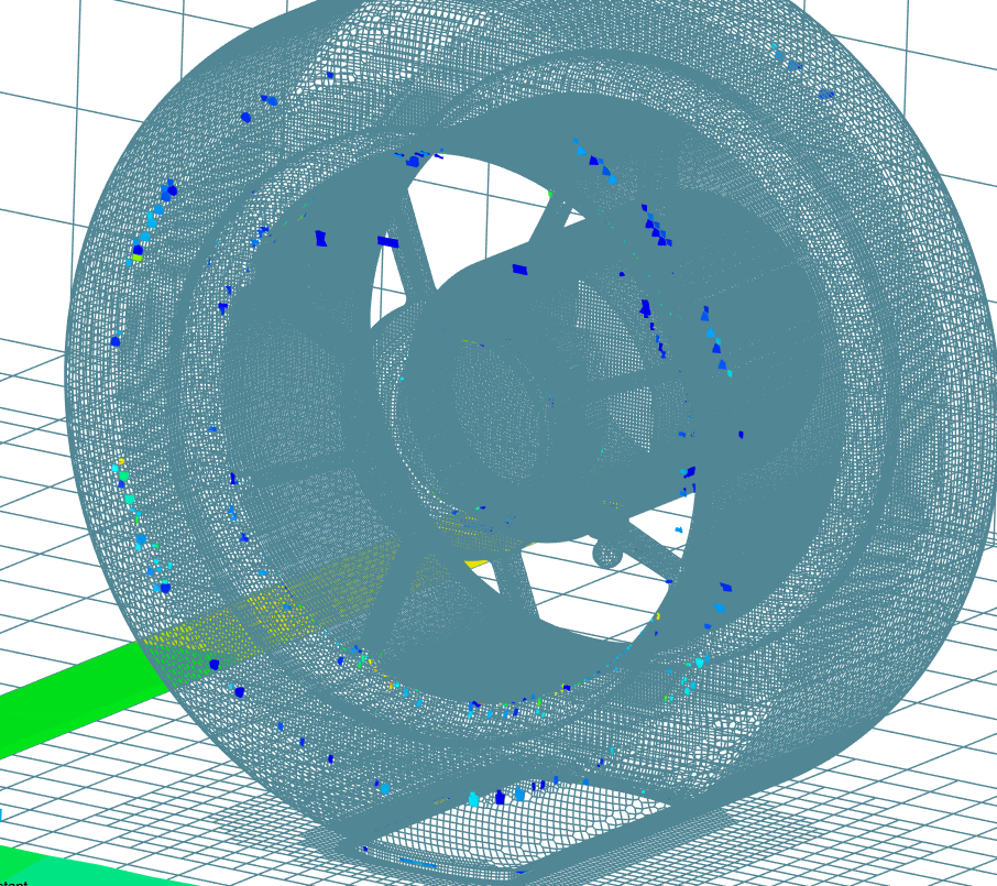
Cells seem to be bad on the wheels inner hub and where the wheel meets the tire. CAD geometry changes might help this.
Wheel test 6.2
- Tolerance increased to 3
Checking faces in error :
non-orthogonality > 65 degrees : 2051
faces with face pyramid volume < 1e-13 : 0
faces with concavity > 80 degrees : 0
faces with skewness > 4 (internal) or 20 (boundary) : 0
faces with interpolation weights (0…1) < 0.02 : 41
faces with volume ratio of neighbour cells < 0.01 : 0
faces with face twist < 0.01 : 2
faces on cells with determinant < 0.001 : 3
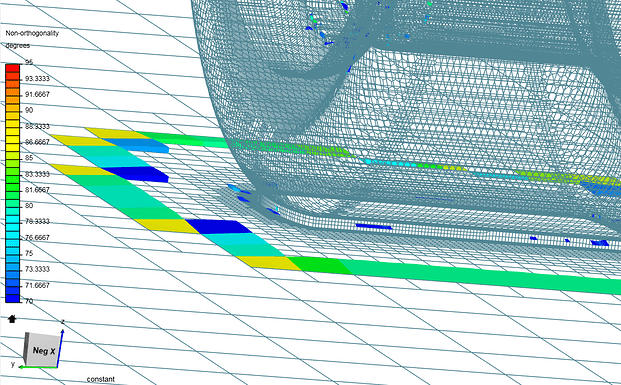
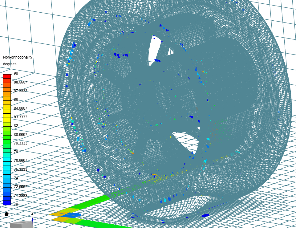
The only change to this test run was increasing the tolerance to 3. I was hoping that the extra allowable snapping length would make the cells conform better to the geometry. This turned out to do very little. Below also shows the dark blue cells with a Non.ortho of 65, which are still acceptable.
Wheel test 7 - Geometry change - hub simplification
- Tolerance back to 2
- Median axis angle 80
- Max Non orthogonality 70
- Relaxed 75
- Bounding box layer addition min thickness reduced to 1e-6
Checking faces in error :
non-orthogonality > 70 degrees : 423
faces with face pyramid volume < 1e-13 : 0
faces with concavity > 80 degrees : 2
faces with skewness > 4 (internal) or 20 (boundary) : 0
faces with interpolation weights (0…1) < 0.02 : 41
faces with volume ratio of neighbour cells < 0.01 : 2
faces with face twist < 0.01 : 2
faces on cells with determinant < 0.001 : 0
volumeRatio
min: 1.0000000000069633
max: 170.08380841806402
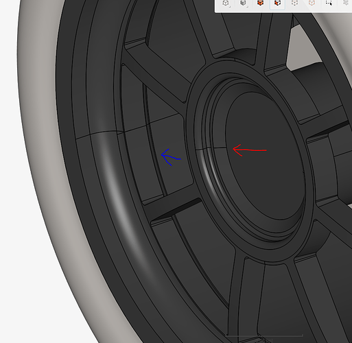
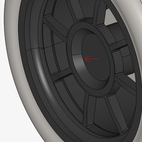
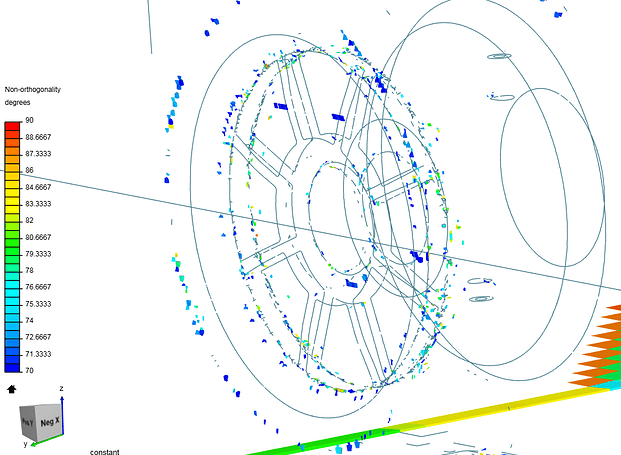
Wheel test 7 had some minor changes to the CAD geometry. By cleaning up the inner hub of the wheel, we can see the difference in Non-ortho faces in this area with the following comparison
Wheel test 6 geometry - more complex hub (red) with spoke intersection (blue)
Wheel test 7 with simplified hub geometry
Non-ortho cells show concentration at the spoke to wheel interface but not at hub
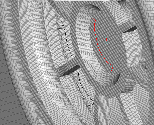
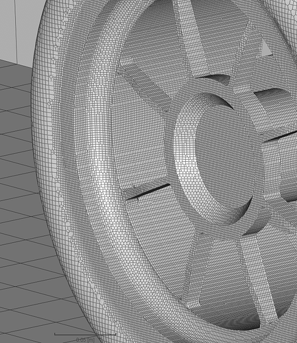
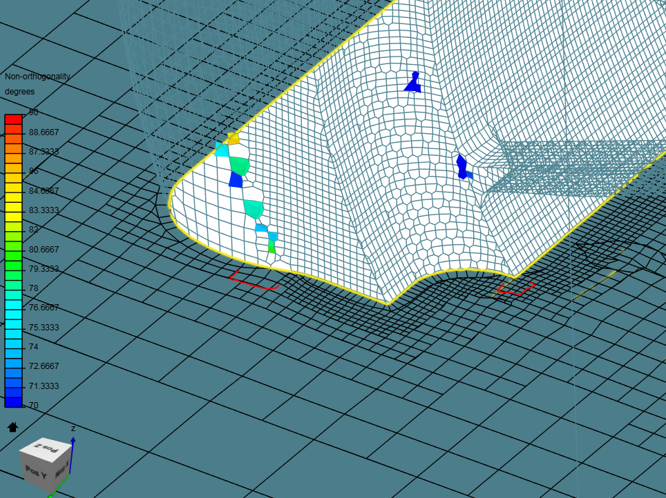
Looking at the actual mesh, it can be seen that the small step where the spokes meet the wheel is causing the problems (1). This is a geometry that should be changed to a simpler form in order to get a better mesh. However the hub mesh is very clean even and is the better meshing option even though the wheel now does not follow the real world geometry. (2)
Wheel test 7.1
- Explicit feature snap
Checking faces in error :
non-orthogonality > 70 degrees : 381 423
faces with face pyramid volume < 1e-13 : 0
faces with concavity > 80 degrees : 1 2
faces with skewness > 4 (internal) or 20 (boundary) : 0
faces with interpolation weights (0…1) < 0.02 : 41
faces with volume ratio of neighbour cells < 0.01 : 0 2
faces with face twist < 0.01 : 0 2
faces on cells with determinant < 0.001 : 0
volumeRatio
min: 1.0000000000069633
max: 171.54233283960056
The only change for mesh 7.1 was the use of Explicit snapping as opposed to implicit. Just this one change reduced the Non-ortho cells from 423 in Test 7 to 381. Other meshing improvements also occurred:
- Faces with concavity were reduced by 1
- Volume ratio of neighbor cells reduced to 0
- Faces with twist reduced to 0
Test 7.1
Wheel test 8 - geometry change - spokes to wheel intersection
- Returned to Implicit feature snap
- Retuned medial axis angle to 90°
Checking faces in error :
non-orthogonality > 70 degrees : 384
faces with face pyramid volume < 1e-13 : 0
faces with concavity > 80 degrees : 0
faces with skewness > 4 (internal) or 20 (boundary) : 0
faces with interpolation weights (0…1) < 0.02 : 0
faces with volume ratio of neighbour cells < 0.01 : 1
faces with face twist < 0.01 : 1
faces on cells with determinant < 0.001 : 0
VolumeRatio
min: 1.0000000000021594
max: 107.21199797538466
The meshing log data shows slightly more Non-ortho cells however Interpolation weights are not at 0. The Volume ratio has also dropped from 171 to 107.
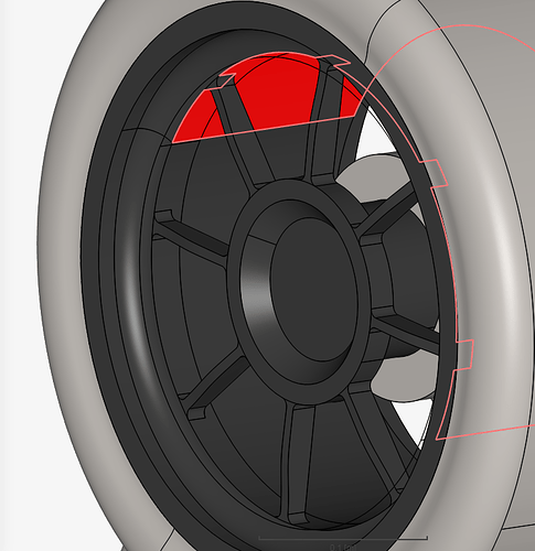
In wheel test 8 I fixed the step at the spokes. The geometry shows a line where the step used to be at the intersection of spokes to the wheel, but the red highlight confirms this is all one flat surface.
The mesh now seems much cleaner in this area.
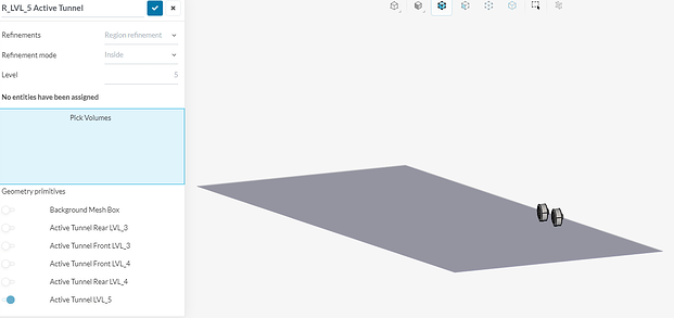
In order to attempt and fix the Non-orthogonal cells at the floor caused by the bounding box layer addition cell termination, i have changed my level 5 region refinement to a flat plate, extending over the entire floor of the bounding box.
For some reason the mesh didnt like my region refinement. The thin, level 5 area doesnt even show up. Now im thinking that level 5 cells are too big for a 0.2m thick region refinement.
EDIT
I did the calculation quickly and with a 1m level 0 cell size, a level 5 would be 0.3125m which confirms my mistake. Level 6 would bring the cells to 0.015625m which would work or conversely, I could increase the level 5 region refinement to 0.03125 meters - the better option for me i think.
The amount of Non-ortho cells has definitely been reduced. I still need to fix the floor region refinement but that comes in test 8.1. I have also noticed that some of the Non-ortho cells have to do with geometry - what i have fixed so far, but others have to do with the cells outside of the geometry - layer addition and snapping processes. These are much harder to change, especially when I am tied to specific boundary layer requirements or total cell count limitations. In the end I may have to accept a certain amount of Non-ortho cells.
Wheel test 8.1
- Testing Explicit feature snap
- Correct lvl 5 region refinement height
Checking faces in error :
non-orthogonality > 70 degrees : 348
faces with face pyramid volume < 1e-13 : 0
faces with concavity > 80 degrees : 3
faces with skewness > 4 (internal) or 20 (boundary) : 0
faces with interpolation weights (0…1) < 0.02 : 94
faces with volume ratio of neighbour cells < 0.01 : 0
faces with face twist < 0.01 : 2
faces on cells with determinant < 0.001 : 23
volumeRatio
min: 1
max: 364.2708799626919
Now that the correct region refinement size is made the area showed up.
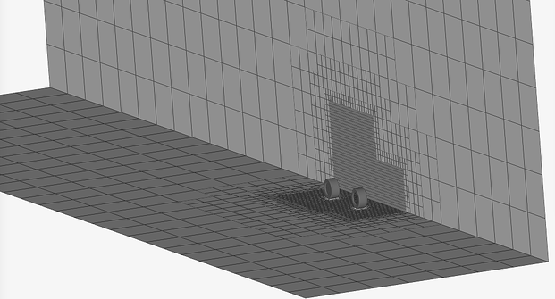
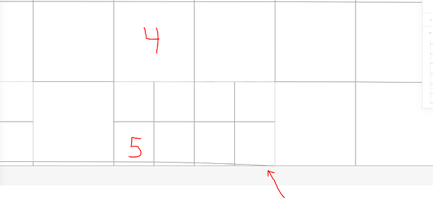
From the side view I now have the bounding box layer addition cells. However, for some reason the region did not mesh over the whole floor even though I set this level 5 region refinement for the exact size of the Bounding box floor. Shown below is the end of this region refinement with level 5 and 4 cells, also with the bounding box layer addition cell that terminates into the ground.
The wheel looks fairly similar with the Explicit feature snapping on. No significant improvement
And where the Bounding box layer addition terminates we have the same problem.
As of now, wheel test 8 had the best results in terms of illegal cells. If I increase the Max allowable Non-orthogonality to 75 then im sure the illegal cell count will drop. This however does not mean the cells are gone, just that the cells between 70 and 75 are now allowed. I do not know how many cells will be “illegal” if I drop the half car simulation down to 70 as well. I also dont know how many cells over 70° will cause problems.
As always simulation is a compromise between many areas. My biggest problem is staying around the 10-11 million total cell count for the half car so that i wont have memory problems with the full car sims. This affects the refinement level of surface and region refinements I can apply. If the refinements are not good enough, the geometry will not be perfectly represented, and the snapping and layering processes will suffer resulting in my situation of illegal cells.
This balance is hard to achieve. My goal here is to get to 95% quality so that the results are somewhat reliable. Any feedback from the experienced users would be extremely helpful so that I can be confident moving forward with “X” amount of illegal cells.
Sorry for the long post haha
