Hello,
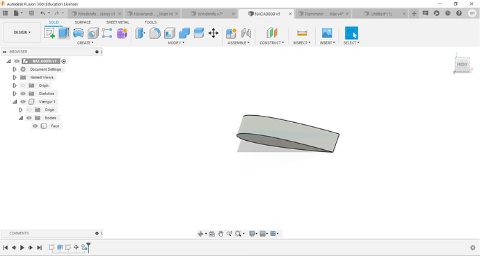
I am creating a very simple wing windtunnel test with the NACA0009 profile with a 10° angle of attack. The material is selected to be seawater because the model will be used in the ocean. I have a couple of problems. Here below is an image of the model.
First of all, what would you suggest select the inital conditions of k and omega to be. I have no idea what to select those as. Do you have some literature that I could read about it. It is turbulent flow in sea conditions. Below is an image of the model.
First of all. I am exporting the model from Fusion as a STEP file, not an STL like in most of the tutorials. I suppose that shouldn’t change anything.
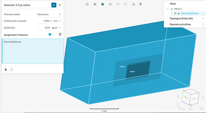
The first problem is that after I have meshed the wing and windtunnel it looks like this:
And I just get this bounding volume. Does this look correct?
Hi there!
As a general tutorial I would recommend you have a look at this one right here: Session 1 of CFD Master Class - just to get a little bit “warm” 
It also helps if you share your project link with us so we can see what is going on inside of your project, the BC (boundary condition)/setup does not look right to me because you do not need any layers at the symmetry face but in height direction (normal to the wing) of the airfoil. I generally recommend looking up some papers regarding parameters like angle of attack, which BCs have been used.
Also (without having access to your project) I would say that your airfoil is 1 component which makes it hard to assign separate conditions so you would have to use the split operation inside of the workbench 
Jousef
2 Likes
Hey @ThorkellH,
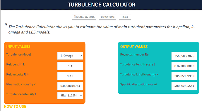
Regarding the initial conditions of k and omega, I usually use this tool.
2 Likes
Here is also a useful post: Defining Turbulent Boundary Conditions !
Best,
Jousef
2 Likes
Hello Jousefm!
Thank you for your reply. Here is the link to the project: https://www.simscale.com/workbench/?pid=1167922557405867888&rru=2b26ff0e-6bd7-46a4-a5fe-8bbd3cc2b26e&ci=15626480-dc30-415c-9e84-b9e93ef331cf&ct=CONVERGENCE_PLOT&mt=SIMULATION_RESULT
I will look at the master class tutorial! Thanks a lot!
I am not sure what you mean by this sentence:
“the BC (boundary condition)/setup does not look right to me because you do not need any layers at the symmetry face but in height direction (normal to the wing) of the airfoil.”
But yes you are correct that the wing is only one component. Why would I need more than one? Is that regarding the symmetry face?
Looking forward to hearing from you!
Really appreciate the help 
Hello Mr. PauloSantos!
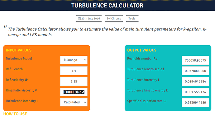
Thank you for your reply. I am simulation a wing being dragged in the ocean at a constant speed of 1.15 m/s. The wing has a length of 2.2 meters but I am using symmetry so the the length I use in the model in Simscale is 1.1m. The kinematic viscosity of seawater at 3° C is around 0.00000167315. And I am using the K-omega turbulence model (no reason why, that was the default chosen in Simscale). How do you select the Turbulence intensity I. I used the option Calculated. Then I get the following results:
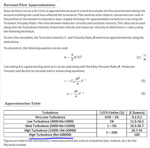
I read the article Yousef sent and there I found the following table:
I approximate that the Reynoldsnumber is within the High Turbulence sector, (see the calculated Reynoldsnumber from the first image, Re = 756058). And if I select High (12%) I get the following results:
The difference is huge! Would you say the latter calculated result was correct? Or how do you use this calculator?
Thank you so much 
1 Like
Hey!
In terms of reference length, I noticed that you’re using the wing length. Usually, the value adopted for this parameter is the chord.
About turbulence intensity, to adopt the value based on the Reynolds Number use to be a good approximation. That is, you can use the classification of very low, low, high, etc.
2 Likes
Thank you so much! I will use chord length from now on. I will use the Reynolds number to set the classification.
@jousefm & @paulosantos
I watched the Master class you recommended @jousefm and also the numerical validation master class. The tutor talked about creating a webinar about turbulence modeling but I can’t seem to find it. Do you know if it was held? Because I would love to watch it.
One question regarding the boundary and initial conditions  I have read the documentation about these aspects but I don’t think the pressure part is clear
The wing will be used at different depths in the ocean. For an example 150 meters depth. But it also has to be used at 900 meters depth as well. If I want to simulate the correct environment situations, how would I select the pressure outlet? Almost every tutorial I have seen uses a pressure outlet with gauge pressure 0 kPa. But that will not be the real case for my wing. Should I select the outlet pressure to be around 1500 kPa (P = rho * g * h = 1028 * 9.8 * 150) for 150 meters depth simulation?
Also, about the initial conditions, almost every tutorial sets the velocity and pressure initial conditions to be zero. If we would set the outlet pressure to be 1500 kPa, shouldn’t I also change the inital condition to 1500 kPa. And I suppose the velocity initial condition doesn’t matter that much.
Your help really matters!
You can use both. Suppose if you use the pressure outlet as 0, the software calculates the pressure inlet as X. If you change the pressure outlet to 1500, the pressure inlet changes to 1500 + X. That is, the pressure gradient is the same. Once the flow behaviour depends on the pressure gradient, the pressure outlet doesn’t affect the flow. It just changes the pressure inlet.
