[Inflate boundary layer - Refinement] - Critical problem

Hi guys,

I am facing two problems when trying to mesh my geometry, maybe someone can help me with these.

PROJECT LINK: [Deleted by author]

1. Inflate boundary layer - Refinement - Critical problem

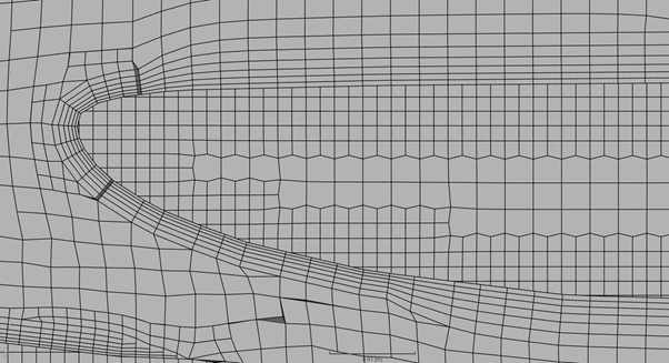
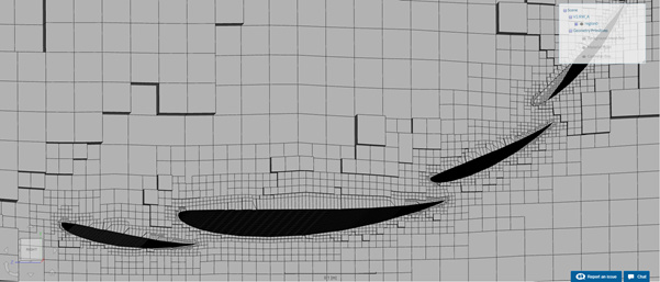
Basically, the problem is that, although I am defining an inflate boundary layer refinement, it does not work. What drives me crazy is that the meshing log seems to indicate that the layers are being created (??), but when inspecting the mesh, they are clearly not there. This problem only affects the layers over the car, not the floor layers.

I thought that the problem may be that the other refinements (i.e. surface ref.) are so high that the mesher chooses them over the layer one, since they imply the creation of smaller cells, in the same way that when several refinement levels coincide in a region, the mesher applies the highest one. Can anyone confirm me if the mesher works in this way?

Anyway, I tried to overcome this problem by changing from absolute to relative size for the external layer height. In this way, if the problem was what I explained above, it should be solved (a size which is defined to be 0.4 relative to the local cell size will always be smaller to that size, no matter how small those cells are…). But layers still did not show up.

Finally, I also tried the following:
-Decrease the level of surface refinement
-Delete the feature refinement
-Decrease the minimum height allowed for the layers in the layer refinement (from 0.001 to 0.00001)

None of these possible solutions have worked. In particular, the mesh “V2.RW_C_0.00001_NoFEAT2” (the last one) is the one in which I have applied all these possible solutions simultaneously.

*Note that the mesh V2.RW_C has exactly the same parameters as the ones used in Homework 2 of the Formula Student workshop series. The only difference is the box size, in order to simulate just the rear wing -to have a smaller mesh in which mesh clips are possible in order to inspect the geometry-. Also in this case no layers appear.

////////////////////////

2. .ZIP uploading (a different problem from the previous one)

Based on the 3rd video shown here:

https://www.simscale.com/forum/t/platform-update-11-12-2017/81267

I was trying to upload a car geometry in .STL format, in such a way that every part of the car is an individual “solid_number”. I was doing it by adding all the individual .STL files to a .ZIP. I want to do it in that way because, later on, I would like to perform an .STL face splitting operation only on the front wing (that is not possible if I upload everything together as a single .STL file).

The problem is that, when using the .ZIP, only one of the .STL files that have been added to the .ZIP is eventually uploaded. All the others just don’t appear. Any idea of what could be happening?
Hi @Jackie_U!

For the first issue may I ask how do you check for inflation of boundary layers? I don’t think you can see the boundary layer inflation on SimScale. @jousefm is there a way to do so that I’m unaware of on SimScale?

Normally the way I do it is to check after the simulation is complete via Paraview which is has its own set of problems and am currently looking for a way to view the mesh before it goes into the simulation accurately. Let you know if I manage to find anything, but as for your current problems, as long as the meshing log states that it is there,then it probably is as I’ve done similar runs and they do indeed show up.

For this issue, I would recommend assembling the entire file before uploading it as a .STL ZIP file to then do the face splitting. STL has always been a problematic format for me when it comes to complex files and I similarly have not found a proper fix for this format. You can do face splitting on OnShape or a offline CAD software if the earlier method dosen’t work.

Do let me know how it goes and if you have any other issues!

Regards,
Barry

P.S I’ve shifted your post to “Project Support” which is more appropriate and also great information on the well structured post!

2 Likes

First of all, thank you so much for your time.

I was thinking pretty much the same as you, but I realized that they are actually visible:
1. While checking the meshes from FSAE webinars, I realized that the layers can easily be observed in the endplates of the rear wing. In my simulations, this does not happen: the cells are just normally refined up to the surface of the wing, but layers do not appear.

2. The layers may also be observed by performing a mesh clip, which sadly does not work for the full car simulations (due to the ↑ # cells)

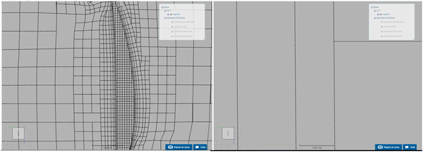
Furthermore, I am sure about the fact that layers are not being created, since this is what looks like my rear wing (mesh clip at 1/2 span):
image

Surprisingly, the layers DO APPEAR for one of the meshes of my project (V2.7).
image
(By the way, in this case they cannot be observed in the endplates, so that trick does not work always… What seems to be reliable is the mesh clip)
The thing is that in this mesh, what I did was to significantly decrease the level of the surface refinements. So the result is horrible, but layers are created… But I would like to have layers in the rest of the meshes -the decent ones-. Or at least understand which factors affect to this issue in order to have it in under control.

/////////////////////
Regarding the .STL issue, I will follow your piece of advice. Could you recommend me an appropriate offline CAD software for the face splitting? I would like to divide my rear wing into 6 surfaces (2 endplates + 4 planes/flaps), so I need to perform the splitting and then join some of the resulting surfaces.

Again, thank you so much.

Hi @Jackie_U!

Yes I have tried the mesh clip but I haven’t been able to obtain what I need. Its probably like you said, the increased number of cells just cause the mesh clip not work properly for some reason.

I will attempt to mesh it out for you on my end to see if I can figure this out and will let you know if I have gotten anything. I don’t see why setting the boundary layer inflation does not produce the desired results but you did have a good guess that the surface refinements somehow overlap the boundary layer inflation and this might actually be the case. We’ll take things one step at a time.

Well unfortunately I have not done face splitting before in an offline CAD software. Referring to this post you can use either SolidWorks or as previously mentioned OnShape where you can perform the face splitting. Definitely assembling it is the proper way to go instead of splitting each individual piece one by one. Also if you read the link, the proper file format is STP not STL apparently so maybe try converting it to STP then upload it here and see if you can perform the splitting operation on SimScale.

Let me know how it goes!

Regards,
Barry

Hi @Jackie_U!

Any progress so far? Looking at your refinements I suggest trying to increase the number of layers to about 5-8 and keeping the expansion ratio to 1.2 first to see if you can get the layer to show up. I suspect that the ratio of 1.05 and 3 layers will not be able to show up due to how small the minimum overall layer thickness is. Try that first, if it doesn’t work then increase the minimum overall layer thickness to maybe 0.01 and see if it shows up.

Do let me know!

Regards,
Barry

Hi @Get_Barried!

What do you think about mesh V2.RW_B? Numer of layers is 5 and exp. ratio 1.5, still no layers are observed.

Could you explain me what is the function of the parameter ‘Minimum overall layer thickness’? I think I am not pretty understanding it.

Thank you again for your help.

Hi @Jackie_U,

I think maybe trying my earlier mentioned configuration, that might work.

About the minimum overall layer thickness I also am not sure what it exactly defines. I have used in a project and it seems to affect what it says i.e “The minimum overall layer thickness”. Whether it is defining it as the entire boundary layer or the individual layers is hard to tell. Either way, it is a minimum value so it should not make your entire layer “disappear” as long as your layer size is larger than the specified value. I haven’t had time to thoroughly investigate this.

Do try out the previous solution and let me know. Also can you tell me which of your simulated geometries are the one with and without boundary layer inflation so I can double check in Paraview?

Cheers.

Regards,
Barry

Hi @Get_Barried!

  1. I have followed your recommendations, using layer refinements with 1.2 for expansion rate and # layers = 6, for different values of the "minimum overall layer thickness”. These are the meshes:
    -V2.RW_C_0.00001_NoFEAT_NoMin_6_1.2 .> "minimum overall layer thickness” as in previous attempts (0.00001 car, 0.0001 floor)
    -V2.RW_C_0.00001_NoFEAT_NoMin_6_1.2_0.01 -> "minimum overall layer thickness” up to 0.01 here

  2. Anyway I suspect that the lower the "minimum overall layer thickness”, the easier it should be for the layers to show up, since I consider it as a threshold below which layers are not created (i.e. if it is zero, then the layers will be created no matter how small they have been defined, isn’t it?

  3. Another guess: may the exporting quality of the geometry be influencing the creation of the layers? I have just realized that the quality in which the .STL were being exported is so low that edges can be observed easily even in a surface which was supposed to feature a high degree of continuity.

  4. All the meshes of the project present have layer refinements defined, but the study focused on this kind of refinement starts from mesh V2.0 onwards. From V2.0 up to V2.7 the base geometry is FUC3M17. The ones which feature ‘RW’ in the name are based on the ‘2017RW’ geometry. In particular, mesh V2.6 was supposed to be my final configuration -until I discovered the inflation layer problem-, so it is somthing like the reference one.

Hey @Jackie_U!

Fantastic. Did you manage to see layers? I will double check those for you.

That is true and it is what I assumed. But I’ve yet to find any concrete documentation for this nor examples so I’ll keep my mind open. By that logic yes the lower the value the more likely it should show up.

That is possible but isn’t this a common project that other users have simulated before? If you refer to this link that talks about STL vs STP, you might be onto something. Lets see whether the issue can be resolved by adjusting the values of the inflation layer before moving onto the geometry as I highly suspect that it is an input issue.

Thanks for the info. With that many meshes and geometries things can get a little confusing :stuck_out_tongue:

Cheers.

Regards,
Barry

Hi @Get_Barried!

None of these new attempts have yielded a mesh in which layers show up. I have also tried using higher quality .STL files but, as you correctly expected, results do not change.

However, although layers do not appear on the car, they do appear over the floor. Note that floor layers were already appearing for the floor with my default parameters, but I had also tried to ↑ the # layers and expansion rate, and they had then dissapeared. Now they are there even after having increased those parameters, so it is at least an improvement.

These are the following attempts I am trying to perform (they can be found right at the bottom of the meshes list in the project; they are just the last 4 ones):

  1. "Minimum overall layer thickness” up to 0.3, just to check the behaviour of this parameter. If our guesses are correct, such a high value should prevent even the floor layers from being created.

  2. "Minimum overall layer thickness” down to 1e-8, and relaxed layer creation parameters (↑ # iterations per layer allowed, less strict layer addition controls, less strict quality controls): I think these should be the most favourable conditions for the layers to be created.

  3. Same as 2, but Surface refinements lowered by 1 level.

  4. Same as 2, but Surface refinements lowered by 2 levels.

Any suggestion will be extremely welcome, as always. Thank you!

@Jackie_U, I believe there might be difficulties if you are trying to inflate layers on a solid with one face, from memory the process should be face splitting then mesh.

Give it a go and let me know!
Darren

1 Like

Ok, I am trying this right now. Thank you for the support!

Hi @1318980!

It seems like the layers are being properly created now, at least in the only-RW case:

image

I am going to repeat the mesh for the whole car, just to confirm that it is definetely working.

@1318980 Could you explain, as far as you know, which are the reasons why the layers were not being created before splititng the .STL geometry? It really interests me, since I do not really catch why this should affect the way the layers are created.

And just another question: if, after being splitted, some of the faces are then joined in topological entites and assigned as so in the refinements, does this affect the way the meshing is done? Or the relevant part is just the surface splitting?

I would be really grateful if you can tell me where I could learn more about how snappyHexMesh (etc.) work.

Thank you!

///////////////////////////////////////////////

Edited: I can confirm that layers are now being created, so the main problem is solved. Thank you.

2 Likes

Hi @Jackie_U, sorry this has taken me so long to get back to you.

My understanding is that if the mesher is creating layers on one face it expects certain things, having more than one face, or patch allows the mesher to correctly inflate layers at interfaces etc. if it doesn’t know where the interfaces are it can throw a lot of problems. Hopefully, someone out there might understand this more technically and will update this answer.

As for your second query, not selecting as part of an entity set will have no effect on how layers are inflated.

Glad this is now working for you.
Darren

1 Like

HI all,
Does boundary inflation and surface refinement tool work on the same surface?