I would like to get a better understanding of how the Fictitious Clearance works. If my geometry contains a gap of 2 mm and I apply a fictitious clearance of 1 mm. Will the solver force the gap to 1 mm or 3 mm?
Hi @BenLewis,
basically when adding a Fictitious Clearance to a contact surface, we add a layer of a fictitious material (with no additional stiffness) with the defined clearance as thickness. On an algorithmic point of view, when it comes down to compute the (signed) contact distance, the solver removes from the actual geometrical distance the fictitious clearance and the result will be used to evaluate the contact state (open/closed) and the contact forces.
So, if your geometry originally has a gap of 2mm and you apply a fictitious clearance of 1mm, the solver would compute a remaining gap of 1mm. After moving one part for 1mm the contact will become active and contact forces will start acting. Using an exact contact algorithm (Lagrangian), the gap will never be smaller than 1mm.
Does this explanation makes sense to you?
Best,
Richard
Hi @rszoeke,
that makes sense.
So if my geometry contains an overlap of 2 mm and I apply a fictitious clearance of 1 mm, the two surfaces will move a relative distance of 3 mm to produce a final gap of 1 mm.
Hello @rszoeke!
I created more runs using “Fictitious Clearance”, for example: https://www.simscale.com/workbench?publiclink=dc509247-35c2-40f5-85fb-b93c64056a34, or https://www.simscale.com/workbench?publiclink=dc733a48-9048-4869-88aa-8da225260178
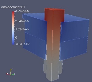
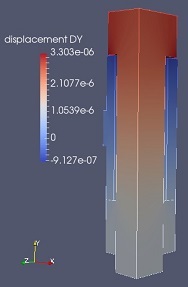
In these simulations I modelled different bolt connections with pretension. I wanted to set a gap (pretension) of 0.1 [mm] (1E-4 [m]) between the bolt head and the compressed part. The Fictitious Clearance was set 0.0001*t, while the simulation time was 1 sec. After the calculation I checked the results and I have seen pretty similar results in both cases; the displaecement between the bolt head and the top of the compressed part is almost the same: 4.2E-6 [m] and 4.1e-6 [m] respectively, which is much much less compared to the value what I would like to see (1E-4 [m]). There has to be something what I misunderstood here with this Fictitious Clearance option, please help to eliminate the problem!
Please see below the result plots of two independent runs showing up the same phenomenon:


Thanks in advance for your support!
Bests,
Csaba
Hello @potyka_csaba,
the problem lies not in the definition of the fictitious clearance, but in the contact type. You are using a penalty contact, which always has penetration of the contact surfaces. A higher penalty coefficient will decrease the inter-penetration, but it will never vanish.
In your first example you have a run called 1srhighpenalty, where I assume you increased the penalty coefficient to see if it has an influence on the results, Unfortunately you forgot to change the value for the contact Bolt-Plate, which has only a value of 1e11, which is not much compared to the stiffness of the involved materials (steel E=1e11).
The penalty value should be about 5-50 times as high as the materials Young’s Modulus.
Increasing the penalty coefficient should improve your results drastically. On the other hand the convergence might become harder and some high value it won’t converge at all.
To check the contact clearance/penetration you can add the contact results global field in the global fields to your run. It has a component called “JEU”, which is the contact clearance on the slave side.
Finally you could try the augmented Lagrange contact type. It does not have contact penetration at all, but is hared to get converged, especially if friction is activated.
Best,
Richard
Hello @rszoeke!
Thanks a lot for your hints! It is right what you mentioned, I tried it and the results became different, however I didn’t checked yet what are the exact values.
Do you have ideas what kind of options do I have to modify or influence to get convergence with Augmented Lagrange in frictional contact?
And what can I check in the log file to learn something about my model conditions?
Bests,
Csaba
Hi @rszoeke,
I have some more questions on this topic:
Does it mean it has the same stiffness as the existing material? So fully equivalent as having changed the gap in the geometry?
This implies that the final distance will add the geometrical distance and fictitious clearance, but it seems contradict your positive reply to:
This implies 1mm in fictitious distance replaced an existing distance of -2mm, and not adding them?
The documentation would definitly benefit from being clearer on the topic, here is what it currently says:
- Fictitious clearance: This allows the introduction of an artificial separation gap between the contact. surfaces. If enabled, the contact is considered to be active when the gap is smaller than the sum of Master clearance and Slave clearance. The clearance can be input as a variable value.
When I first read this, I didn’t think it could be negative to create a virtual interference/imposed pressure or would do anything other than influence the active/inactive contact monitoring output. More importantly, each of the terms Fictitious and Clearance are confusing the nature of the feature, it seems to be more a Modified Offset.
Thanks for asking for a clarification @tansari .
You are right, there have been some contradicting answers from me in this thread.
So, let’s clarify with all possible scenarios:
| Initial State | Fictitious Clearance Value | Final State |
|---|---|---|
| 2 mm GAP | 1 mm | 2 mm GAP (no contact active) |
| 2 mm GAP | -1 mm | 2 mm GAP (no contact active) |
| 2 mm GAP | 3 mm | 3 mm GAP (contact active) |
| 2 mm OVERLAP | 1 mm | 1 mm GAP (contact active) |
| 2 mm OVERLAP | -1 mm | 1 mm OVERLAP (contact active) |
| 2 mm OVERLAP | -3 mm | 2 mm OVERLAP (contact inactive) |
Does this make now more sense?
Best,
Richard
Thank you @rszoeke , I had to re-read the definition and this table makes sense with it.
the contact is considered to be active when the gap is smaller than the sum of Master clearance and Slave clearance . The clearance can be input as a variable value.
But now I also realize that my understanding of the topic may be missing something ![]()
- What is the application for Fictitious Clearance only overriding the distance when the value is more than the initial one?
- What is an active contact?
- If I wanted to simulate pressure between two press-fit parts in a given range of interference values, can Fictitious Clearance be used for this?
- If yes, does the feature behavior described above means that I am expected to start at a high interference value and use Fictitious Clearance to lower its value from there?
- If not, is the only way of doing this to use a set of every geometry I want to simulate?