To me, that is not restricting rotation around the pin when a down force is applied on the left side of the pin in that image (also remember there is not much rotation in degrees) …
Hi @ROHIT_SR,
For me, there is no question that the front fixation should be modeled as a pin joint.
What is not clear to me is if the translation of the front pin should be fixed or free. If you want to model the performance of the halo in the test rig the pin translations should be fixed because the test rig looks to be very rigid. However, if you want to model the performance of the halo on the vehicle then I would either:
-
Model the front pin with free translations in the longitudinal and lateral directions, for a worst case scenario; or
-
Model the cockpit stiffness for more accurate results.
From your discussion above it appears that the purpose of your simulation is to determine if the halo structure will pass the FIA standard. Therefore, your deflection results will best match the test rig results if the pin translation is fixed in all directions.
Hello Rohit,
I’m doing a simulation for a university Thesis which also involves the halo structure. I was wondering if i could have your permission to use your halo dimensions and whether you could access them to me?
Kind Regards, Eliott
Hi @egabbitas ,
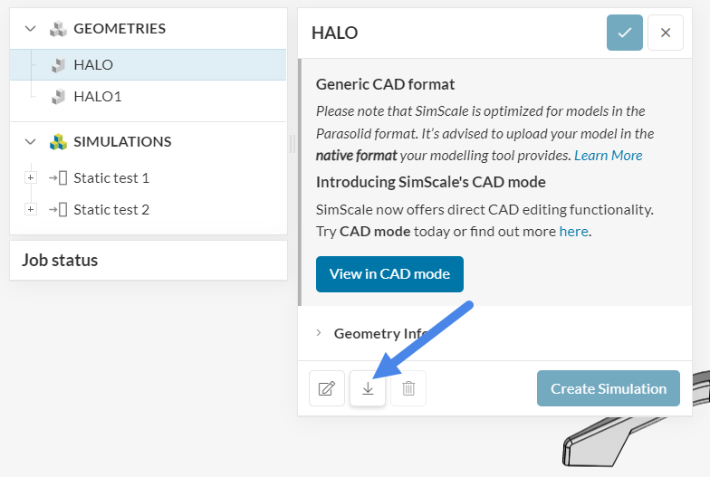
All files in a community project are public, so you can download the geometry straight from the project (link).
Cheers
Thank you so much!
