thank you sir 
Nice project @ROHIT_SR!
For the “pinned support” you can use a “remote displacement” . Just set the remote point into the center of the pin and free the rotation around the axis direction.
One additional hint: instead of using a “very fine” 1st order mesh, you could increase the result accuracy by getting a bit coarser on the fineness and use a 2nd order mesh instead.
Best,
Richard
Hi @ROHIT_SR,
@rszoeke bet me to it, but for what it’s worth I have copied your project and modified it to demonstrate how to model a pin joint. You can see my modified project here:
[!!!THIS LINK IS NO LONGER AVAILABLE!!!]
Please take a look at the following simulations:
- Static test 1 - Run 2 D_z fixed
- Static test 1 - Run 3 D_z free
- Static test 2 - Run 3 D_z fixed
- Static test 2 - Run 4 D_z free
The “D_z fixed” runs have the front pin translation in the z-direction fixed.
The “D_z free” runs have the front pin translation in the z-direction unconstrained.
How the pin translates in real life depends on how stiff the cockpit structure is relative to the halo structure. If the cockpit is much stiffer than the halo then the front pin will act as though its translation is fixed. If the cockpit is much more flexible than the halo then the front pin will act as though its translation is free. If the stiffnesses are about the same then the front pin will partially resist translation but not completely. In this case the stiffness of the cockpit structure will need to be modeled to get accurate results.
As a guide the front pin translates by about 12 mm under 116 kN of longitudinal load when it is unconstrained.
Gut feeling says the test setup looks pretty rigid and would translate much less than 12mm and that is a setup used to approve different manufacturers I suppose ![]()
Agreed, but I suspect that the cockpit on the vehicle would be significantly more flexible than the test rig.
hi sir,
SORRY FOR LATE RESPONSE. ![]()
all point are rigidly attached to the cockpit.

so, I don’t think there is any pinned joint in the cockpit BECAUSE the total displacement should be less than the 3 mm in case 1 and less than 45 mm in case 2.
(correct me if it’s wrong) @DaleKramer @rszoeke @jousefm
LINK
THANK YOU,
ROHIT
Hi ROHIT, @ROHIT_SR
I think there is very much room left for interpretation of that document.
If I were trying to have my halo approved by the committee, I would want to know specifically, the rigidity of the test structure that the test halo would be mounted to in order to measure the required deflection of the halo under load.
The document does not specify that.
I do believe that they intend the rear joint to be rigidly fixed in all degrees of freedom to the vehicle.
However, I think that the front joint described in 3.5 is a pinned joint on the test fixture (if that is the actual test fixture that they have shown us in the document and which is used for approval testing).
- 3.5 Front Fixing Axis
The cylindrical joint connecting the Central Pylon
to the Front Bracket.
I think that sometimes specification documents fail to fully specify what is intended 
Dale
HI @DaleKramer sir,
you are right. there is info in detail about this project. only 3 company in the have permission to manufacture this f1 halo.
so, FINALLY, can I used pinned joint or fixed join for this project? @rszoeke @jousefm @DaleKramer @BenLewis
if it’s pinned THAN I will change the results image in this post.
THANK YOU
ROHIT.
With all the supplied info, I personally would use a pinned point…
But how is he gonna decide the dimension of the hole  ? Its not mentioned in the pdf
OK SIR ,
I WILL CHANGE THE RESULTS
i am waiting for other thought also.
thank you,
rohit
Call the people who test it, or take a few guesses and see how the diameter affects results ???
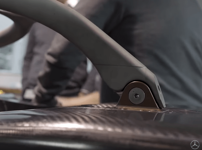
According to me, there is no need to give a pin joint as if you closely look at the front end of the halo, you will realize that the contour on the halo’s surface fit perfectly into the clamping surface(like soul mates  ) thus restricting all the 6 DOFs. So I don’t think that there will be a drastic affect of changing the current configuration and assigning new constraints.
To me, that is not restricting rotation around the pin when a down force is applied on the left side of the pin in that image (also remember there is not much rotation in degrees) …
Hi @ROHIT_SR,
For me, there is no question that the front fixation should be modeled as a pin joint.
What is not clear to me is if the translation of the front pin should be fixed or free. If you want to model the performance of the halo in the test rig the pin translations should be fixed because the test rig looks to be very rigid. However, if you want to model the performance of the halo on the vehicle then I would either:
-
Model the front pin with free translations in the longitudinal and lateral directions, for a worst case scenario; or
-
Model the cockpit stiffness for more accurate results.
From your discussion above it appears that the purpose of your simulation is to determine if the halo structure will pass the FIA standard. Therefore, your deflection results will best match the test rig results if the pin translation is fixed in all directions.
Hello Rohit,
I’m doing a simulation for a university Thesis which also involves the halo structure. I was wondering if i could have your permission to use your halo dimensions and whether you could access them to me?
Kind Regards, Eliott
Hi @egabbitas ,
All files in a community project are public, so you can download the geometry straight from the project (link).
Cheers
Thank you so much!

