Errors with table velocity input?

Hello everyone, hope i can find some help.

I’m working on a simulation of wind pattern (pression and velocity variations) around an high rise building project.
Made a lot of tests to achive a simulation of a wind “power profile”, i.e. a velocity inlet that increase with altitude.

I tried starting the meshing process uploading the same geometry both in STEP and Rhino native formats, making different types of meshing, but always missing the last step, facing a simulation issue in the end.

Actually, i think i’ve wasted a good amount of core hours :frowning:

Right now i have a mesh made starting with a STL file, that, despite the less surfaces control, made the operation much faster and the meshing result seems enough defined for my purposes. ( i think to study a more detailed behavior of the building skin on a second project, where i think i’ll upload a much more defined model of a portion of the skin structure).

The problem is that i’m facing again analysis run issues, and i think it could be related to the table velocity input i created, but actually i don’t really understand what i’m doing wrong.

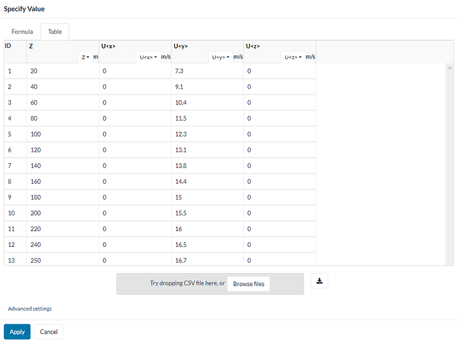
As you can see from screenshot, on a column i inserted the altitude values, and on the others the velocity values, respectively, keeping Ux and Uz null, having my inlet surface normal corresponding to y axis.

Is really this input that makes simulation keeping on failing, or, despite the different meshes approaches tried, i made again a bad mesh? I looked to many tutorials and to similar public projects reagarding wind analysis on buildings , but i’m still not so sure on which should be the optimal fineness for my project.
Thank you so much for your time!
Minato Skyport

1 Like

Hi @badio93

I will look at your project and will come back with a suitable solution as soon as possible.

Thanks
Ani

1 Like

Thank you very much Ani;
Notice that i’m running a test with fixed velocity, no dependencies on height, and it is running properly!

Yeah just saw that. It had already converged in first 500 iterations.

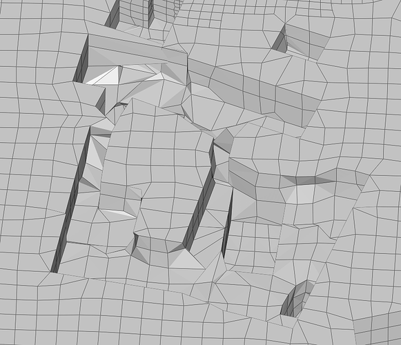
But your mesh quality may make it difficult to simulate the same situation when you are using an inlet velocity file.
You should increase your refinement as these result would be meaningless if the mesh doenot capture the geometrical features prorpely.


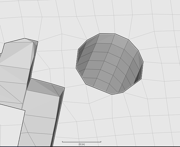
Like here in the below img, the cylindrical building is not meshed properly and thus takes the shape of polygon. This will give you meaningless results even if your simulation has converged.

Thanks
Ani

Hi @badio93!

Just leaving this post from my colleague Darren here which might help you at some point: How can I define an Atmospheric Boundary Layer in SimScale

Best,

Jousef

Thanks again.
Well, i came up with that low res through many efforts with way better quality meshes, so just wanted to test out the differences and see what could be the problem, i’ll certainly improve that.

Anyway, even if i could create a good simulation with a better mesh and a constant inlet, i would like to use the height-related inlet…you think that the table i posted was well writed?

I noticed that in the previous tests with table velocity input, the running crash appeared in the very first loading of the calculation, so i couldn’t see any run log after the crash.

Thanks Jousef, i’ll throw an eye on it!

I found the answer in Darren’s post.

“between points defined as X, Y, Z the velocity will be linearly interpolated, so it is important that good resolution is given close to the 0 velocity edge, furthermore, several ‘poles’ of points are recommended. i.e. if the inlet boundary was in the YZ plane normal to X, and Z low was the floor, a CSV where Z varies for example [0.01, 0.02, 0.04, 0.08, 0.16, 0.32, 0.64, 1.28, 2.56…] and Y varies [-200, -100, 0, 100, 200] giving poles of points at -200m etc in the increasing distance from the ground if the ground was located at Z=0.”

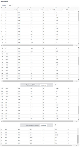
So, taking a look to the csv example posted by Darren next to the quoted part …all the vectors that i define should have starting coordinates related to plane position in global reference, said so, if my inlet XZ plane finds at Y=-800, all my vectors should have Y=-800 on table.
And, to have a more accurate simulation all along the width of the wind tunnel, it may not be enough to create only one “vertical line” of starting points on the plane…in this case, i should create more vectors vertical “groups” changing X coordinate while keeping, of course, Y fixed.
In the end, all the vectors that share the same altitude, will have same Uy value.

Made a test and in fact wind profile look finally realistic, with velocity inlet values increasing with altitude.
Used three interpolation sets of points, at X=300 X=0 X=-300, with Y constant=-800, which is the coordinate of my inlet face in global axis reference.

Hope it will help other construction designers :slight_smile:

4 Likes