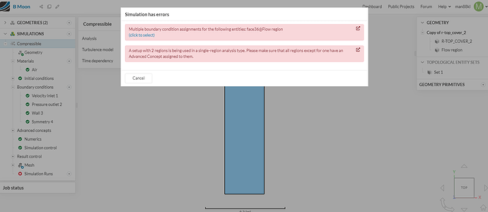
It have error in below link project. Please acces it to solve the issue for me. Thanks.
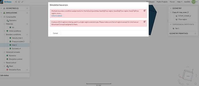
Hi there, each face can get only one boundary condition. As the message indicates some of them have more than one. If you click on the (click to select) option that is highlighted in blue, you can check these specific faces, and fix your boundary conditions accordingly.
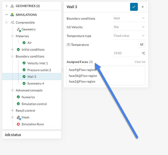
Here, you have set both slip wall and symmetry bc for some of the faces.
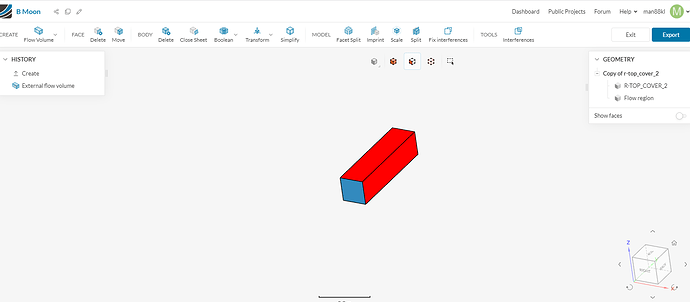
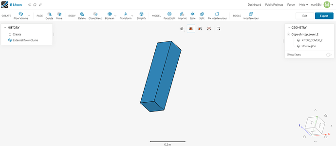
Also, you will need to delete all solid parts after the flow volume is extracted. You can do this using the CAD mode: CAD Mode | CAD Preparation & Upload | SimScale
Best regards,
Fillia
Do you mean in this page? some surface in blue. After I click it, it change to red. Don’t know how to change its Boundary condition.
Would you please do easier way to update for me. I want to have streamline diagram. Thank you.
This is the CAD mode environment, You can change the boundary conditions here:
Which I see you already did 
Fillia
I try to follow you instruction to delete solid parts , but in above page, it don’t have command of ‘delete solid parts’ . Please help to access my project to update for me. Thanks.
Please help to solve above, or access to my project link to update for me. Project link shown as folowing. Thanks.
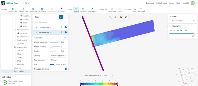
I try to make stream line diagram, but just got as above picture. Please help to solve it, or access to my project link to update for me. My project shown as above. Thanks
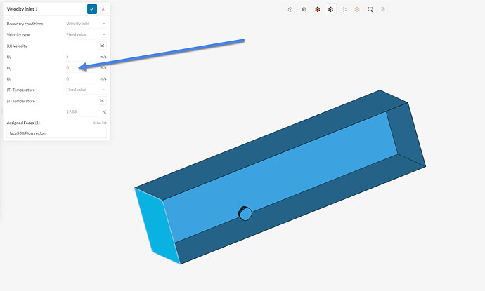
Hi, you have used the wrong direction for the velocity inlet. It should be Uy according to the coordinate system, not Ux.
This is why the streamlines do not show. You will have to rerun the simulation with the correct boundary conditions.
Best regards,
Fillia
