Here’s a link to my project;
This is a rudder for a radio-control boat. I’m having this 3D-printed to replace the existing rudder on my boat, which lacks steering authority.
For the purpose of learning, I want to simulate water flowing around the rudder in two situations:
- Boat moving straight ahead at 15 MPH (6.7056 m/s)
- Initiating a turn, where the rudder is at an angle of attack to the water (either by rotating my model in the “wind” tunnel flow, or (if the former is not possible) by applying X and Y flow velocities calculated based on the AOA I wish to simulate.
I set up a straight-line simulation by creating the mesh, defining the “wind” tunnel, defining the fluid material, setting the fluid velocity, etc.
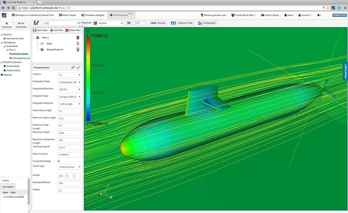
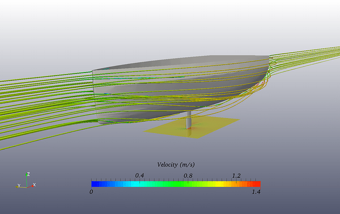
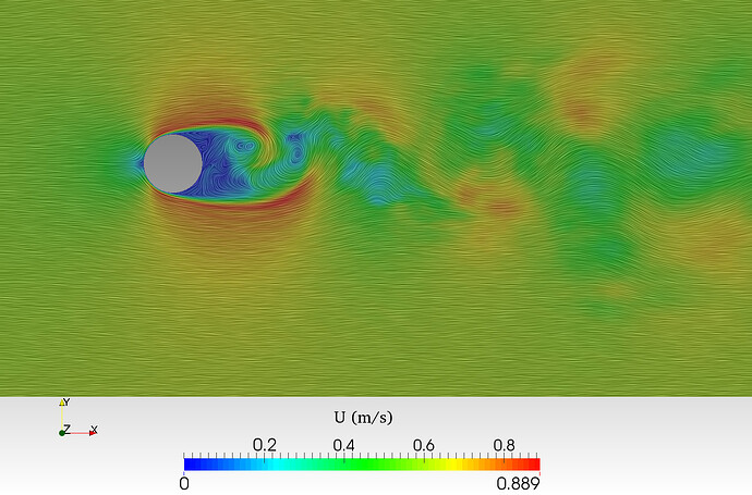
I’m interested in (and struggling to) generate results like this:
Any help is appreciated. Thanks!
Hi @mculik5!
Having a look at your project  Can you update the links at the very bottom? They do not work somehow.
Best,
Jousef
@jousefm - Thanks!
Strange - on my end, they don’t work if you left-click on them, but if you right-click and open in a new tab, they do work.
Let me know if that does/doesn’t work for you.
Hi @mculik5!
Just edited your post. Was wondering because I was on my mobile phone and could not open it so I just pasted the pictures directly. 
The following things I noticed have to be changed before we can continue:
-
You have to make sure that the geometry is watertight! Otherwise some parts of the mesh just vanish after the meshing process.
-
The geometry has to be split which can be done inside the platform or using a CAD program of your choice.
Generating results as shown in the pictures is not very hard. If we fixed the two points mentioned above we can start setting up a simulation case and after that download the results to post-process them inside Paraview.
Let me know if you have any further questions and enjoy your weekend!
Jousef
No worries @mculik5!
- Usually the information that the geometry is watertight can be found in the geometry event log but does not always have to be there

This is also important when using the snappyHexMesh operation because otherwise, it might simply mesh both “sides” of the model - inside and outside. To define what “side” we want to mesh we define the so called Material Point which decides if we want to have an external flow simulation or internal one.
- A tutorial for the splitting process can be found here: STL Split Geometry. This would also be helpful in this case to click on a surface and hide it to see if there are any defects that are hidden which might cause some glitches in the mesh. The splitting process does also leverage our potential to create boundary layer cells more easily. We had some cases in the past where just one solid was causing trouble generating the inflated boundary layer.
Was everything clear so far? Let me know if I missed something!
Best,
Jousef
2 Likes
@jousefm - Thanks for the additional details. Over the weekend, I re-drew the rudder in Fusion 360 (instead of SketchUp). I excluded the vertical steering arm, since I believe that’s where the watertight issue was coming from in the SketchUp STL export, and it’s not relevant to this analysis (as it’s in the air behind the boat, not the water).
I started a new project using a STEP file for the rudder, and confirmed it’s watertight. I wasn’t quite following the geometry splitting, but since that appeared to be relevant only to STL files, I skipped it.
Here’s the project - https://www.simscale.com/workbench/?pid=947979951857616781.
I ran two simulations - one with the boat moving straight ahead, and one with a Z component to the water velocity to attempt to simulate a turning AOA on the rudder.
At this point, I’m interested in two things:
- Confirming that my simulation setup is appropriate.
- Learning to create images like those above so I can “see” the flow around the rudder.
Thanks!
Hi @mculik5!
The geometry looks quite good!  Things I could notice at first glance and need to be fixed:
-
Increase the domain size - it is still too small at the moment!
-
You did turn off the boundary layer creation - for more flexibility use the parametric option for the mesh and create an inflate boundary layer for your model
General information about the dimensionless wall distance yplus can be found here:
Tell me if that helped you. @Get_Barried & @vgon_alves: If you can find some other settings that are not optimal for the setup please let our users @mculik5 know.
Thanks guys and all the best!
Jousef
2 Likes
@jousefm - By “domain size,” I take it you mean the size of the “wind” tunnel?
Regarding the boundary layer stuff, I’ll read through that tonight and re-run the mesh/simulations.
Thanks!
Exactly @mculik5 - increase the size of the bounding box! If you have any questions feel free to ask.
Best,
Jousef
FYI, I’ve been very busy at work the past few days, so I haven’t had a chance to play around with this. I’m not giving up. Will try to do some more work on this ASAP.
1 Like
Take your time @mculik5! We are here if you need something 
Cheers and happy SimScaling!
Jousef


 Can you update the links at the very bottom? They do not work somehow.
