Hi Csaba (@potyka_csaba),
I’ve taken a look at your simulation. Here are my comments.
You can find my copy of your project here
[!!!THIS LINK IS NO LONGER AVAILABLE!!!]
Loading Equations
Your loading equations are correct.
- Bolt clearance: 0.0001*t*(t<=1)+0.0001*(t>1)
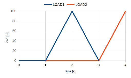
- Internal pressure: 30000000*(((t-1)*(t>1))-((t-2)*(t>2)))
- Fixed temperature: 293.15+(500*(t-2)*(t>2))
The equation for bolt clearance could also be expressed in one of the following ways:
- 0.0001*t*((t<=1)+(t>1))
- 0.0001*(t-(t-1)*(t>1))
All three forms are equivalent. I prefer the two alternative forms above because there is a clear distinction between the magnitude and the shape of the load (0.0001 is only used once). This just makes it less prone to mistakes when making adjustments.
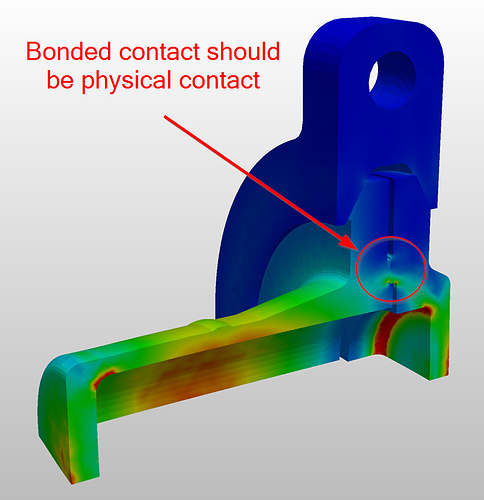
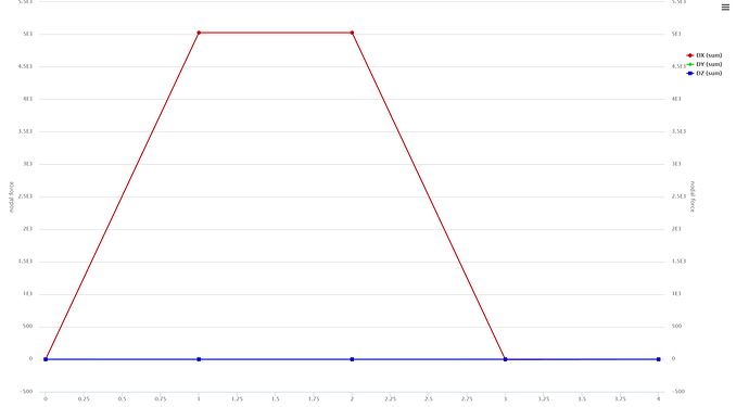
It looks to me that bolt tension drops off because of the mechanics of the structure. The seal ring, between the two flanges, is fixed on both sides with a bonded contact. This means that the two flanges cannot separate when the internal pressure is introduced. Instead, the flanges rotate about the seal ring taking pressure off the bolt. The fictitious clearance is maintained, it’s just that the internal pressure is so great that it completely unloads the bolt. Replacing the bonded contact with a physical contact allows the two flanges to separate.
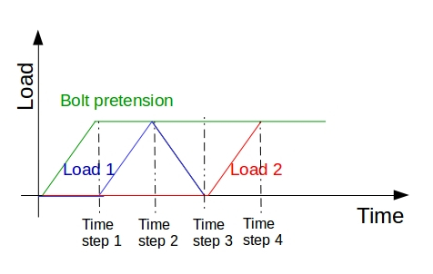
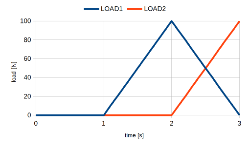
You can verify this by moving the the pressure and temperature loads one time step further along (see Simulation 2 - Run 1). Bolt load only drops off when the pressure load is introduced (time step 3).
Alternative approach
I’ve included an alternative approach to solve this problem (see Reactor03 FO Fine - Run 1). The main differences are:
- Quarter model instead of full model
- Overall finer mesh
- Augmented Lagrange contacts instead of sliding or bonded contacts (most significant change)
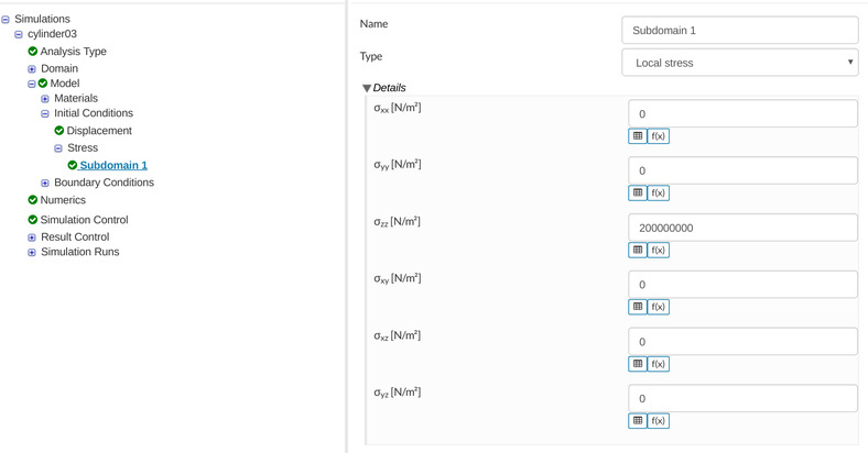
- Stress initial condition instead of fictitious clearance
- Reduced magnitude of elastic support
- Manual time stepping instead of automatic.
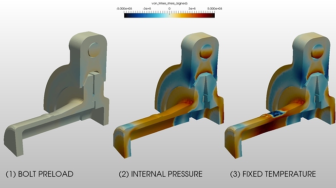
Here is a screen shot showing each time step.
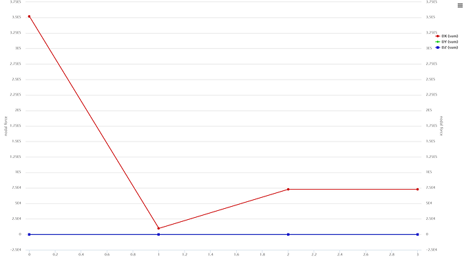
With the new constraints bolt force now increased with the introduction of internal pressure. This is to be expected because the bolt preload is not enough to overcome the large internal pressure (flanges separate).
Stress Difference Plots
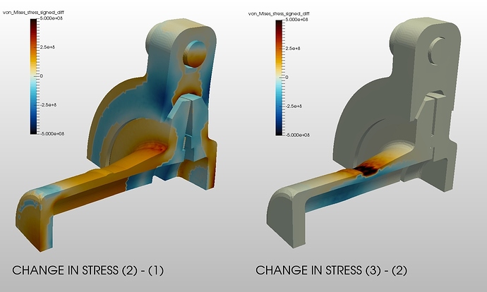
Here is a screen shot showing the change in stress from one time step to the next. This is useful for fatigue applications where the static stress does not contribute to the cyclic damage of the structure.
These plots were generated using a programmable filter in ParaView. I will post the code shortly.
Comments for SimScale
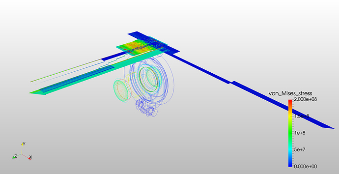
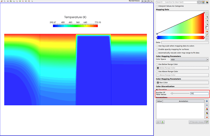
The results files for these simulations look odd when first opening in ParaView (see screen shot below). Using the Extract Block filter fixes the problem but this should not be necessary. Can somebody take a look at this please?
@afischer and @vdoelle, this model is very prone to the “selection bug”. You may want to take a look at this one.
Final Thoughts
This looks like a very interesting project. If I’ve misunderstood your application please let me know. I’m sure we can work out a suitable solution.
Regards, Ben

