Documentation
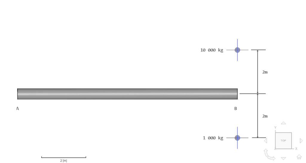
This validation case belongs to solid mechanics, with the case of a circular cantilever beam with two off-center point masses connected at the free end. The test case aims to validate the following parameters:
The simulation results of SimScale were compared to the reference results presented in [NAFEMS]\(^1\)
The geometry used for the case is as follows:
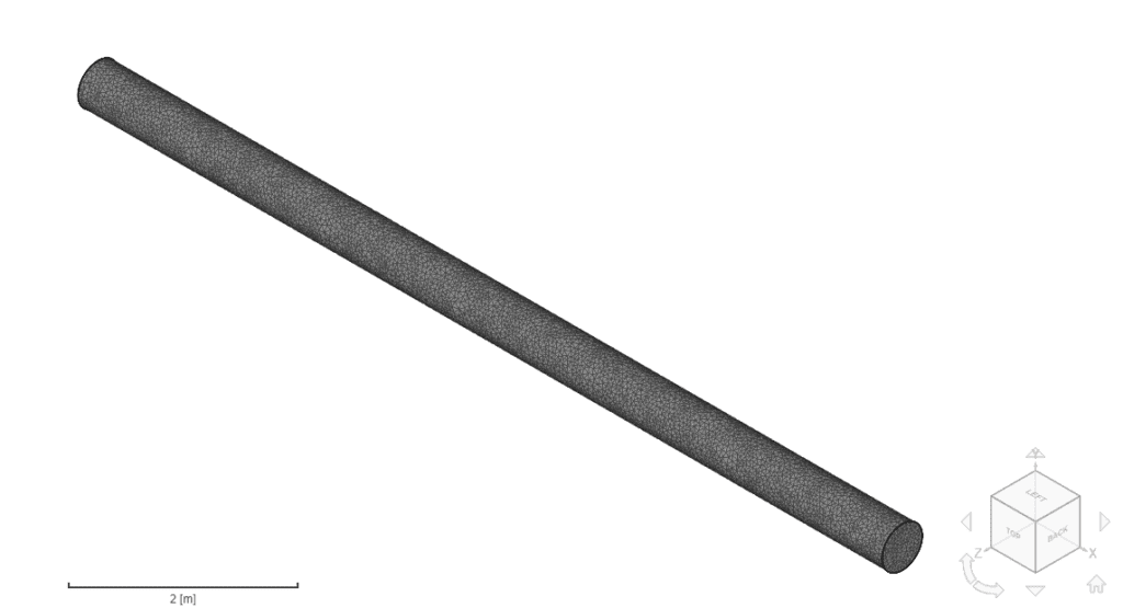
It consists of a straight beam of length 10 \(m\) and a circular, constant cross-section of radius 0.5 \(m\).
Tool Type: Code_aster
Analysis Type: Frequency Analysis
Mesh and Element Types:
The tetrahedral meshes were computed using SimScale’s standard mesh algorithm and manual sizing. The following table shows an overview of the mesh characteristics:
| Case | Mesh Type | Number of Nodes | Element Type |
|---|---|---|---|
| A | Standard | 32 663 | 1st order tetrahedral |
| B | Standard | 118 696 | 1st order tetrahedral |
| C | Standard | 240 757 | 2nd order tetrahedral |
Material:
Boundary Conditions:
The reference solution presented in [NAFEMS]\(^1\) is of the numerical type. It is presented as the first six natural oscillation frequencies of the cantilever beam with the connected remote point mass. The values are presented in Table 2 alongside the comparison with SimScale results.
Comparison of the first six natural frequencies for the run cases with the reference solution:
| Mode | NAFEMS | Case A [Deviation] | Case B [Deviation] | Case C [Deviation] |
|---|---|---|---|---|
| 1 | 1.723 | 1.739 [+0.9%] | 1.731 [+0.5%] | 1.767 [+2.6%] |
| 2 | 1.727 | 1.750 [+1.3%] | 1.734 [+0.4%] | 1.771 [+2.5%] |
| 3 | 7.413 | 7.573 [+2.1%] | 7.448 [+0.5%] | 7.593 [+2.4%] |
| 4 | 9.972 | 10.040 [+0.7%] | 9.982 [+0.1%] | 10.186 [+2.1%] |
| 5 | 18.155 | 18.344 [+1.0%] | 18.141 [-0.1%] | 18.524 [+2.0%] |
| 6 | 26.957 | 26.941 [-0.1%] | 26.768 [-0.7%] | 27.302 [+1.3%] |
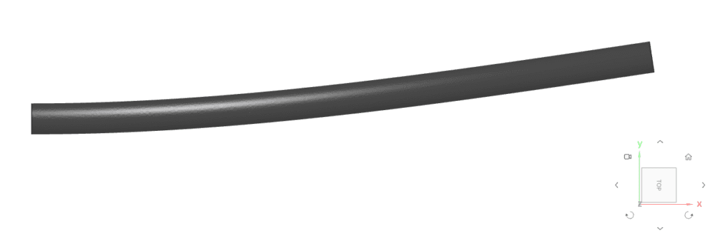
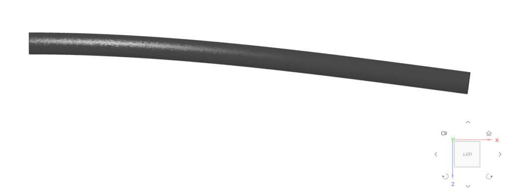
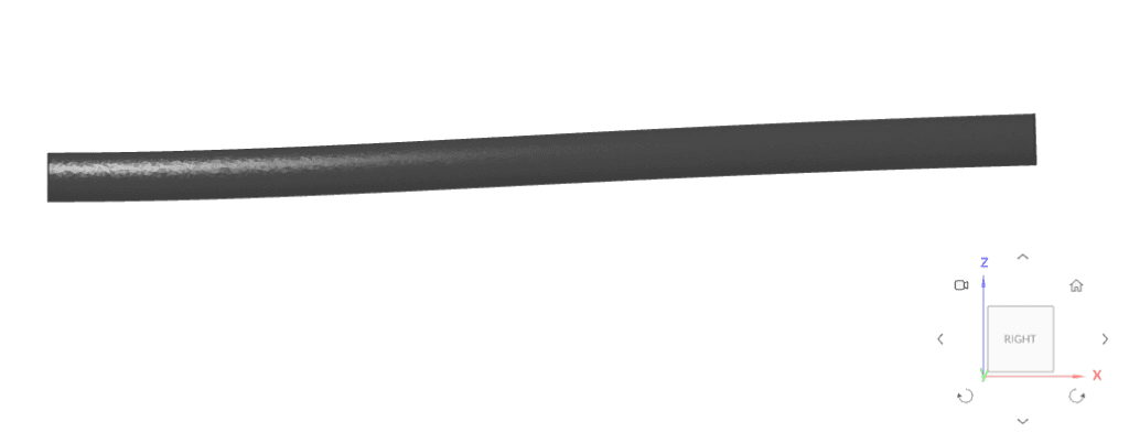
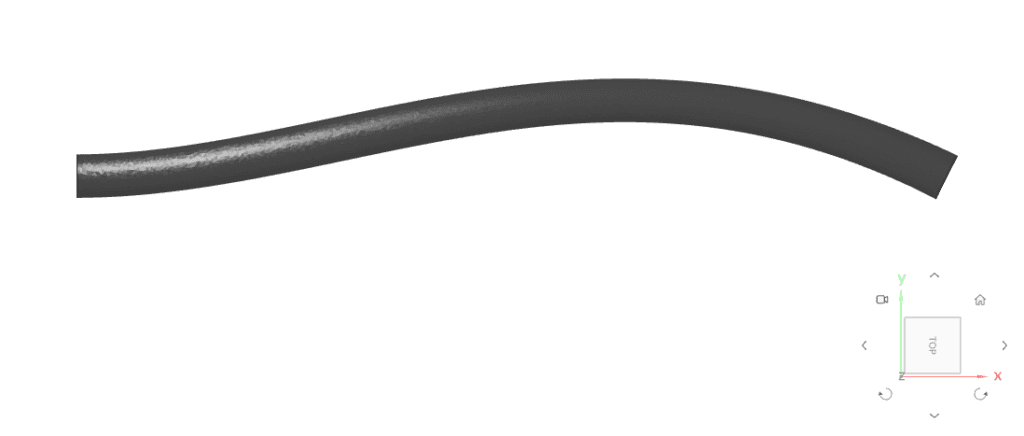
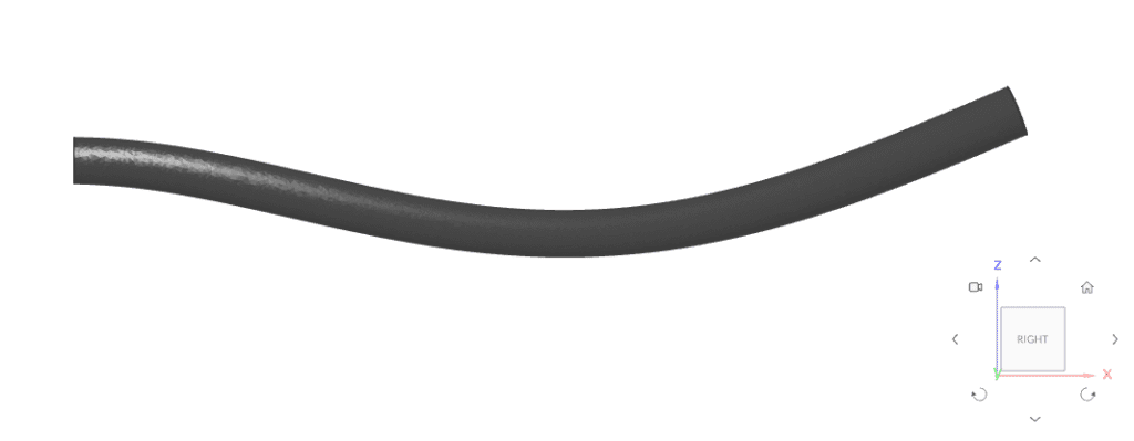
Following are the deformed shape plots for each mode, as taken from case C:

References
Last updated: December 6th, 2021
We appreciate and value your feedback.
Sign up for SimScale
and start simulating now