Validation Case: Quadcopter Ground to Air Thrust
This validation case belongs to fluid dynamics. This test case aims to validate the following parameters for a quadcopter drone thrust in ground proximity:
- Ratio of Thrust at ground to Thrust in free air.
The simulation results of SimScale were compared to the research performed by C. Paz, E. Suarez and C. Gil, J. Vence published in the paper “Assessment of the methodology for the CFD simulation of the flight of a quadcopter UAV” in November 2021\(^1\).
The analytical method used in the research paper is derived from measurements for a slightly different quadcopter, with blades of the same radius.
To compare SimScale to the results in [1], an analysis of different distances from a quadcopter drone to the ground is performed and the thrust ratios are compared. Distance from ground and rotor radius dimensions are taken as shown in Figure 1:
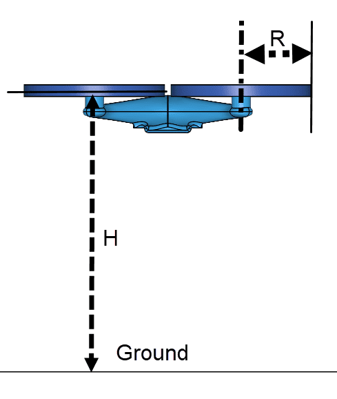
Geometry of Quadcopter
The quadcopter geometry used for this case can be seen below:
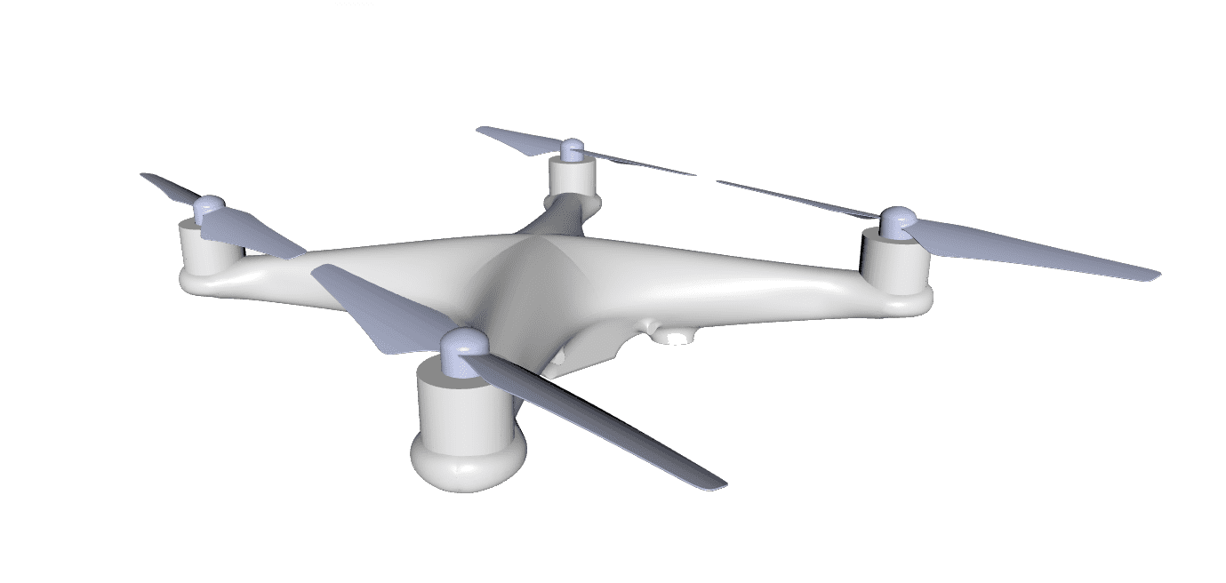
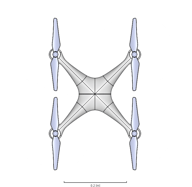
It’s a DJI-Phantom quadcopter with the landing leg and camera removed. the DJI-Phantom is a quadcopter drone used in multiple applications. The rotor blades of the drone were all aligned as seen in Figure 3:
Analysis Type and Mesh
Analysis Type: Steady-State, Multi-purpose analysis with MRF rotating zone, using the k-epsilon turbulence model.
Mesh Sensitivity Analysis
The Multi-purpose mesher algorithm with hexahedral cells was used to generate the mesh. Multiple meshes with incrementally increasing refinement were generated in parallel using the automatic meshing functionality before comparing different height setups.
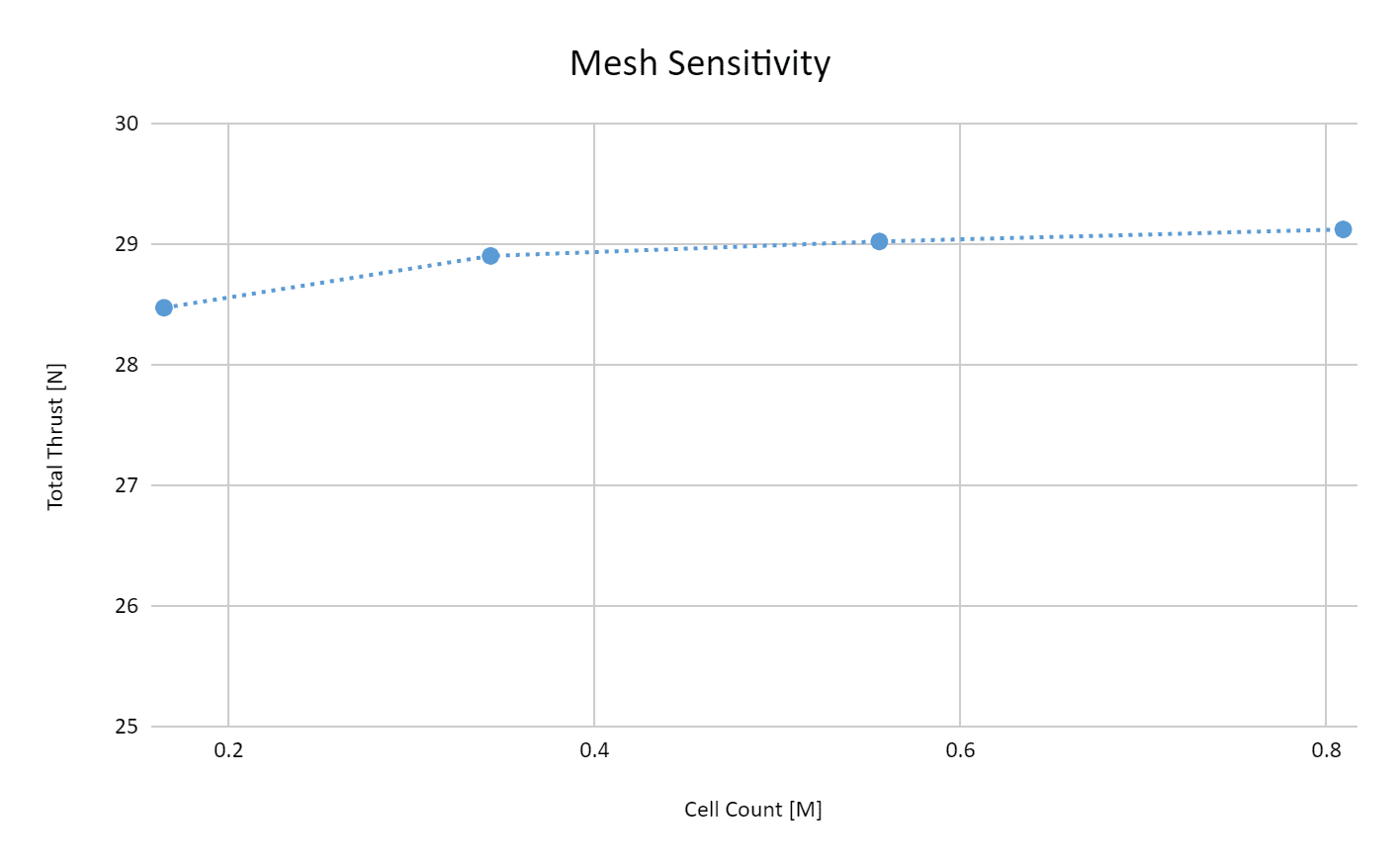
As seen in Figure 4 the total thrust converges to 29 \( N \) for a cell count higher than 0.5 million cells, with a deviation of less than 1 % between 0.55 and 0.8 million cells. Therefore all results with a cell count higher than 0.55 are considered mesh insensitive.
Drone Propeller Study
A validation case for single propeller has already been documented and can be accessed below where a further investigation into the mesh of a single propeller has been performed.
Simulation Setup
Material:
- Air
- \((\nu)\) Kinematic viscosity: 1.529e5 \(m^2/s\)
- \((\rho)\) Density: 1.196 \(kg/m^3\)
Boundary Conditions:
- Inlet & outlet:
- Total gauge pressure \(P\) of 0 \(Pa\)
- Turbulent kinetic energy \(k\) with an inlet value of 3.75 e−3 \(m^2 s^2\)
- Specific dissipation rate \(\omega\) with an inlet value of 3.375 1 \(s\)
- Slip walls on the rest of the domain faces to represent an open-air environment.
Reference Solution
Thrust Changes Due To Ground Proximity
To compare the results gained by SimScale with the published results \(^1\) the Sanches-Cuevas Equation is used.
$$ \frac{T_{IGE}}{T_{OGE}} = \frac{1}{1-(\frac{R}{4H})^2-R^2(\frac{H}{\sqrt{(d^2+4H^2)^3}})-(\frac{R^2}{2}) (\frac{H}{\sqrt{(2d^2+4H^2)^3}}) -2R^2 (\frac{H}{\sqrt{(b^2+4H^2)^3}})K_{b} } \tag{1} $$
Where,
- \( T_{IGE}\) = Thrust of the propellor in closed ground condition
- \( T_{OGE}\) = Thrust of the propellor in free air condition
- \(R\) = Radius of the rotor
- \(H\) = vertical distance to the ground
- \(d\) = distance between the adjacent rotor axis
- \(b\) = diagonal distance of the rotor axis
- \(K_{b}\) = Imperical body lift coefficient (Value for this study \( K_{b}=2\))
Result Comparison
Comparison of the \( \frac{T_{IGE}} {T_{OGE}} \) ratio obtained from the SimScale results against the results obtained from [1] is given below:
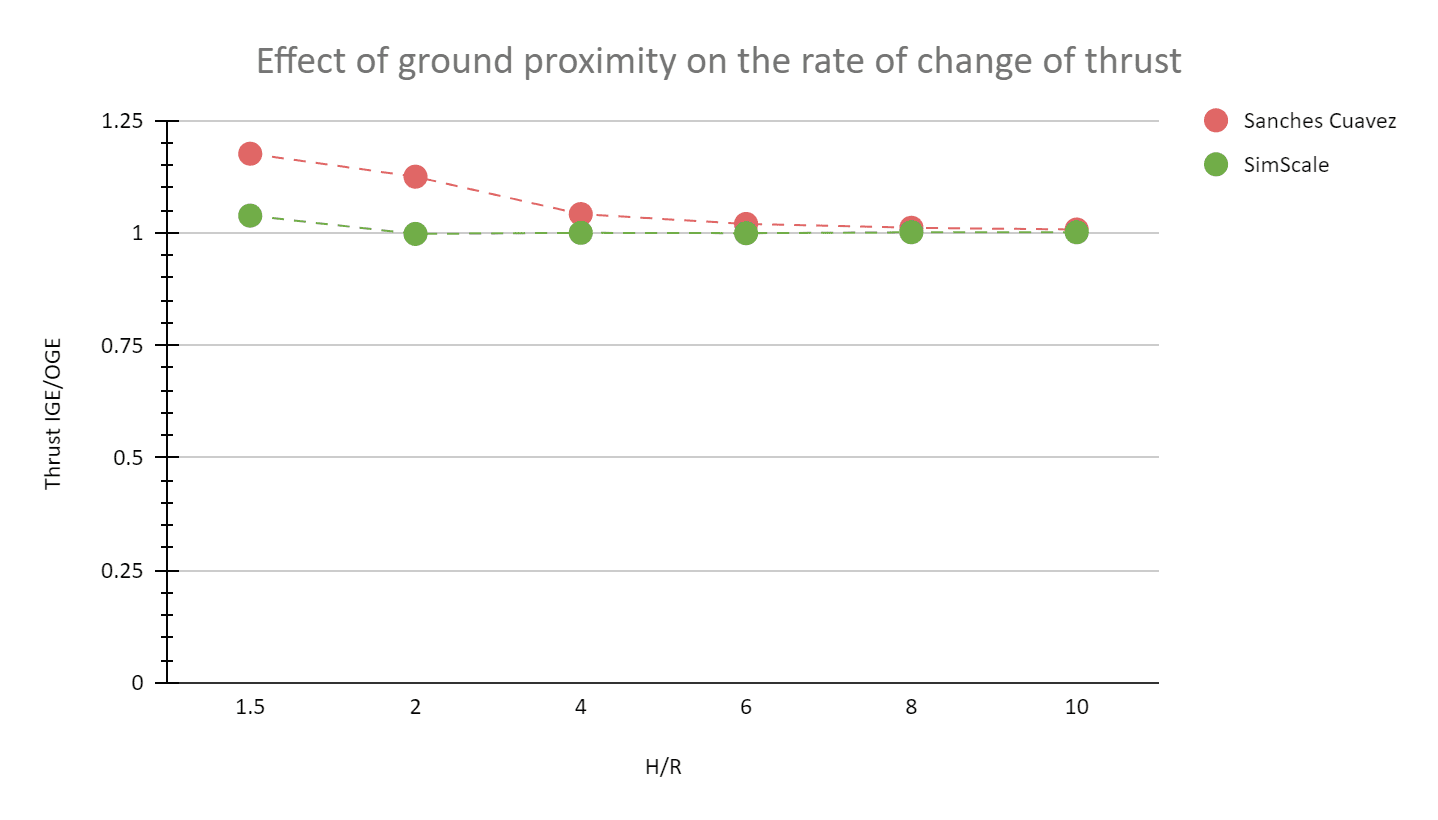
The SimScale result for the quadcopter shows a good correlation with the Sanches Cuevaz curve, especially for height to radius ratios higher than four. The percentage of error is high for low \(H/R\) ratios because the SimScale data is compared with the analytical data, which does not account for close-to-ground effects, SimScale does.
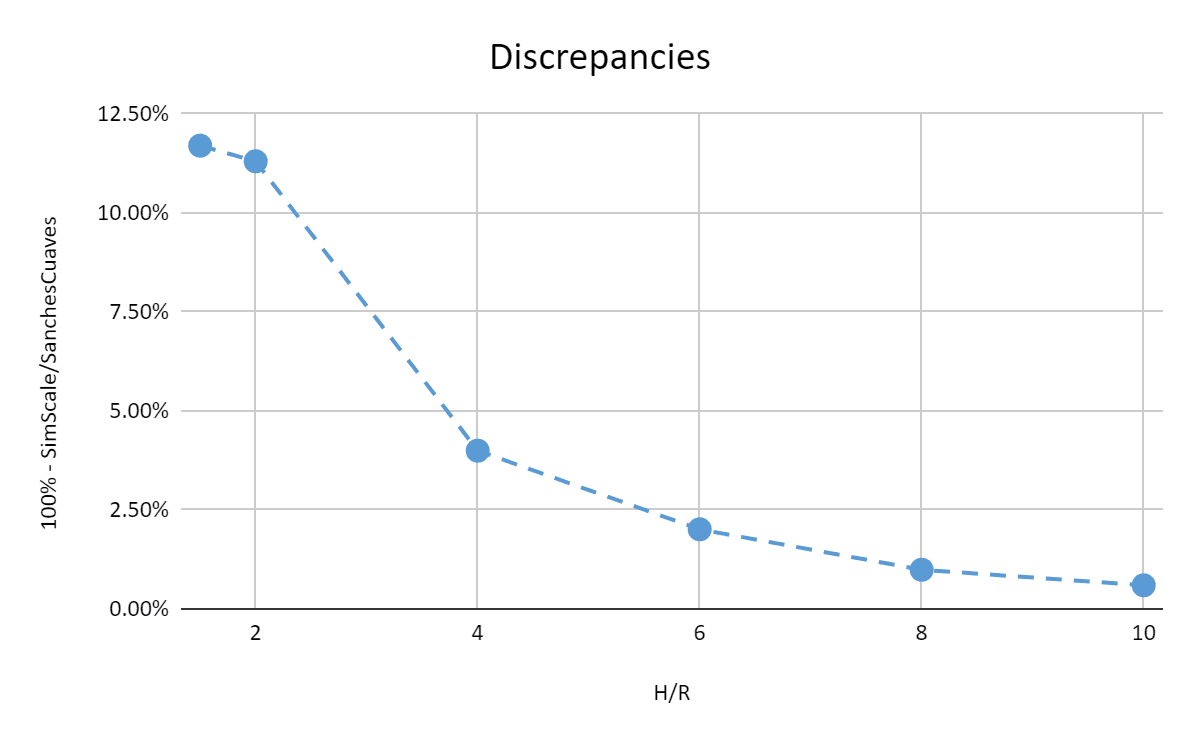
Below are the discrepancies for each run:
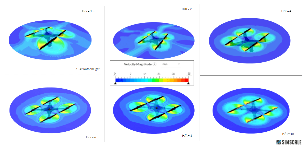
In the following Figure 7, the velocity is plotted at the rotor plane for different heights. It is noticeable that for higher heights the influence of the ground is not noticeable.
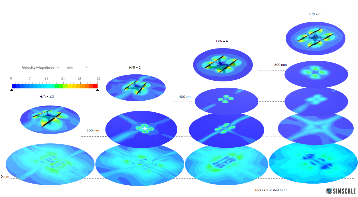
The velocity at different heights can be seen in the figure below. As expected with the increasing distance of the quadcopter from the ground, the velocity at the ground is slower and more diffuse which decreases the thrust of the quadcopter.
Note
If you still encounter problems validating you simulation, then please post the issue on our forum or contact us.
Last updated: August 13th, 2024
Did this article solve your issue?
How can we do better?
We appreciate and value your feedback.


