websights

Fill out the form to download

Required field
Required field
Not a valid email address
Required field
Required field
  • Set up your own cloud-native simulation in minutes.

  • Documentation

    Validation Case: Bimetallic Strip Under Thermal Load

    This validation case belongs to thermomechanics, with the case of a bimetallic strip under thermal load. The aim of this test case is to validate the following parameters:

    • Thermomechanical solver
    • Multiple materials and bonded contact

    The simulation results of SimScale were compared to theoretical computations derived from [Roark’s]1.

    The geometry used for the case is as follows:

    geometry model bimetallic strip thermomechanical validation case
    Figure 1: The strip external faces are split to create the needed points for boundary conditions.

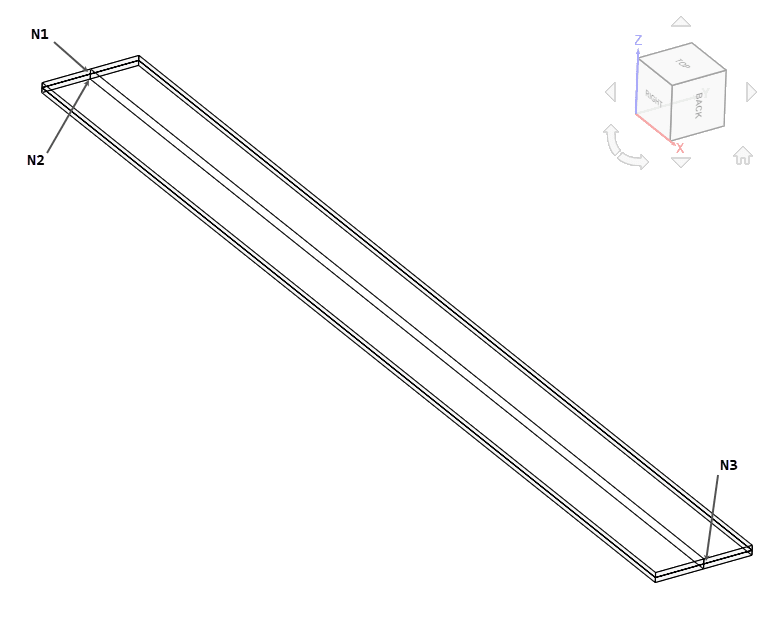
    It represents a strip with length l of 10 m, width w of 1 m and thickness t of 0.1 m, composed of two strips each with thickness ta,tb of 0.05 m. Nodes N1 and N3 are located at mid-thickness and node N2 is located at the bottom surface as shown in figure 1.

    Tool Type: Code_Aster

    Analysis Type: Thermomechanical steady state with static inertia effect

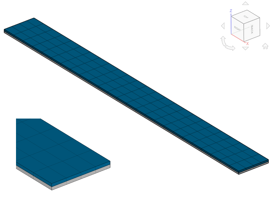
    Mesh and Element Types:

    Mesh TypeNumber of
    Nodes
    Element Type
    2nd order hexahedral3652Standard
    Table 1: Mesh details

    The hexahedral mesh was computed locally and uploaded into the simulation project.

    hexahedral mesh bimetallic strip thermomechanical validation case
    Figure 2: Finite elements hexahedral mesh used for the simulation (closer view on the left)

    Material:

    • Top Strip:
      • Elastic Modulus Ea= 200 GPa
      • Poison’s ratio νa= 0
      • Density ρa= 7870 kg/m3
      • Thermal conductivity κa= 60 W/(mK)
      • Expansion ratio γa= 1e-5 1/K
      • Reference temperature 300 K
      • Specific heat Cpa= 480 J/(kgK)
    • Bottom Strip:
      • Elastic Modulus Eb= 200 GPa
      • Poison’s ratio νb= 0
      • Density ρb= 7870 kg/m3
      • Thermal conductivity κb= 60 W/(mK)
      • Expansion ratio γb= 2e-5 1/K
      • Reference temperature 300 K
      • Specific heat Cpb= 480 J/(kgK)

    Boundary Conditions:

    • Constraints:
      • N1 restrained with dx=dy=dz= 0 m
      • N2 restrained with dx=dy= 0 m
      • N3 restrained with dy= 0 m
      • Fixed temperature T= 400 K applied on top and bottom surfaces
    • Contacts:
      • Bonded contact between the strips

    The reference solution is of the analytical type, as presented in [Roark’s]1. It is given in terms of the displacements of the free end of the strip and the stress at the bottom surface:

    dx=l(TT0)γa+γb2

    dz=3l2(γbγa)(TT0)(ta+tb)tb2K1

    σbottom=(γbγa)(TT0)EbK1[3tatb+2EaEb(tatb)3]

    K1=4+6tatb+4(tatb)2+EaEb(tatb)3+EbEatbta

    The computed solutions are:

    dx=0.015 m

    dz=0.75 m

    σbottom=50 MPa

    A comparison of displacements at point N3 and stress σXX at point N2 with theoretical solution is presented below:

    POINTFIELDCOMPUTEDREFERROR
    N3DX [m]0.0150.0150.00 %
    N3DZ [m]0.74790.75-0.28 %
    N2SIXX [MPa]48.763150-2.47 %
    Table 2: Results comparison and computed errors

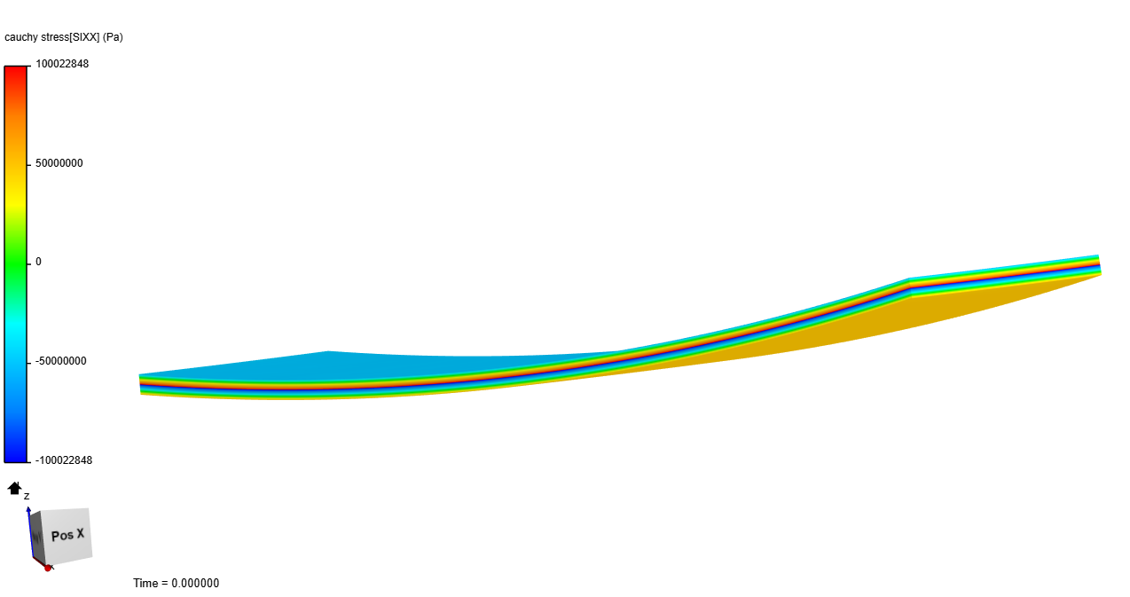
    Illustration of the deformed shape and stress distribution on the bimetallic strip below:

    stress contours developed due to deformation in simscale postprocessor thermomechanical
    Figure 3: Deformed shape and stress contour on the bimetallic strip

    Advanced Tutorial: Thermomechanical Analysis of an Engine Piston

    References

    • (2011)”Roark’s Formulas For Stress And Strain, Eighth Edition”, W. C. Young, R. G. Budynas, A. M. Sadegh

    Note

    If you still encounter problems validating you simulation, then please post the issue on our forum or contact us.

    Last updated: May 19th, 2021