Documentation
This 3D punch contact validation case belongs to solid mechanics. This test case aims to validate the following parameters:
The simulation results of SimScale were compared to the analytical results derived from [NAFEMS_R94]\(^1\).
The geometry consists of a punch (DGHIJK) on top of a foundation (ABCDEF). The 3D punch has a 10 \(mm\) radius fillet at the edge of the contact with the foundation. Figure 1 shows a wireframe of the geometry:
Due to the symmetry of the problem, only a quarter of the model is used for the simulations. These are the coordinates for each of the points:
| A | B | C | D | E | F | G | H | I | J | K | |
| x \([mm]\) | 0 | 0 | 0.1 | 0 | 0 | 0.1 | 0 | 0.04 | 0 | 0 | 0.05 |
| y \([mm]\) | -0.2 | -0.2 | -0.2 | 0 | 0 | 0 | 0 | 0 | 0.1 | 0.1 | 0.1 |
| z \([mm]\) | 0 | 0.1 | 0 | 0 | 0.1 | 0 | 0.4 | 0 | 0 | 0.5 | 0 |
The following dimensions are used in the creation of the geometry:
| Geometry Feature | Dimension \([mm]\) |
| Punch diameter | 100 |
| Punch height | 100 |
| Foundation diameter | 200 |
| Foundation height | 200 |
| Fillet radius at the edge of the punch contact | 10 |
Tool Type: Code_Aster
Analysis Type: Dynamic
Mesh and Element Types: The meshes used in this project were created in SimScale with the standard algorithm.
| Case | Element Type | Nodes | Element Technology | Solution Method | Contact Smoothing | Penalty Coefficient | Coefficient of Friction |
| A | 1st Order Tetrahedral | 32101 | Standard | Penalty | On | 1e14 | 0 |
| B | 2nd Order Tetrahedral | 50226 | Reduced Integration | Penalty | On | 1e14 | 0 |
| C | 1st Order Tetrahedral | 32101 | Standard | Penalty | On | 1e14 | 0.1 |
| D | 2nd Order Tetrahedral | 50226 | Reduced Integration | Penalty | On | 1e14 | 0.1 |
Find below the mesh used for cases B and D. It’s a standard mesh with second-order tetrahedral cells.
Material:
Boundary Conditions:
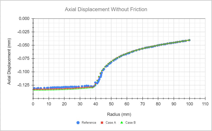
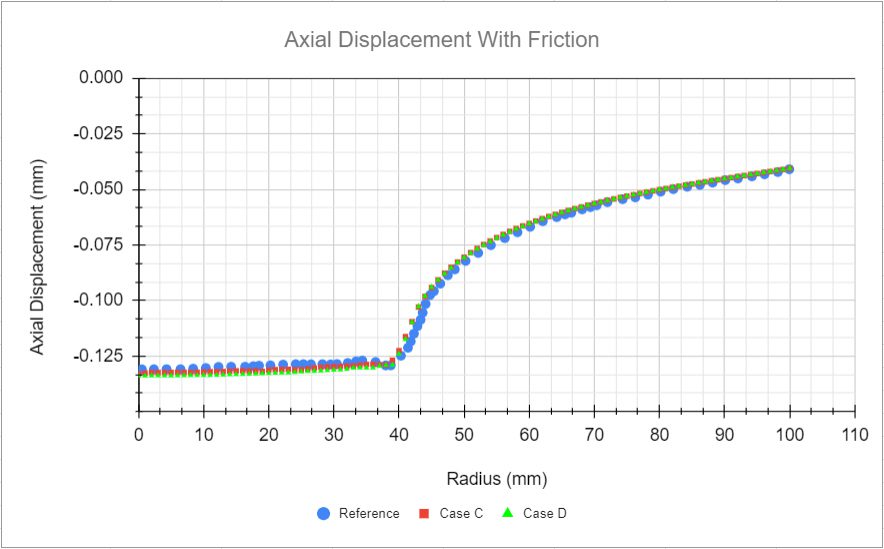
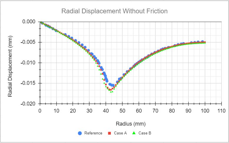
Comparison of the displacements and the normal pressure of the nodes on edge DE. The values of reference in all figures were calculated with MSC.MARC and extracted from [NAFEMS_R94]\(^1\) with WebPlotDigitizer.
The first plot is a comparison between the axial displacements from the cases without friction and the reference values:

Now, comparing axial displacement from the cases with the friction and the reference values. Similarly to the previous case, a very good agreement is observed here:

Now, still analyzing the results over the DE edge, we will compare the radial displacements obtained with SimScale to the reference ones.

Figure 6 shows contours for \(y\) displacement, in meters, for case D:
References
Last updated: September 30th, 2021
We appreciate and value your feedback.
Sign up for SimScale
and start simulating now