Documentation
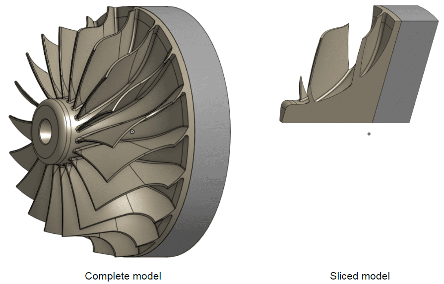
The cyclic symmetry boundary condition enables the modeling of a section of a 360° cyclic periodic structure and reduces the computation time and memory consumption considerably. Required settings include the center and axis of the cyclic symmetry as well as the sector angle. The master and slave surfaces define the cyclic periodicity boundaries.

The following analysis types support the usage of this boundary condition:
The axis is defined by the Axis origin and the Axis direction. The definition of the Axis direction and the Sector angle has to be in accordance with the right-hand rule, such that it defines a rotation that starts on the slave surface and goes to the master surface. For a graphical example, see the picture below:

It’s required to define the axis of revolution and the sector angle explicitly. The Sector angle has to be given in degrees. Available ranges for the angle are from 0° to 180° and only values that divide 360° to an integer number are valid.
Meshing for master and slave faces
Generally, the more refined of the two periodic boundary surfaces should be chosen to be the Slave. In the case of cyclic symmetry, this will, in most cases, not matter since both faces should be meshed with nearly the same element sizes.
The effect of the cyclic symmetry condition is to map the deformations of the master face onto the slave face, transforming them through the sector rotation. This creates the cyclic effect but does not constrain the body in the radial, tangential, or axial directions. Proper additional constraints must be added to prevent rigid body motions.

Important Information
Last updated: February 13th, 2025
We appreciate and value your feedback.
Sign up for SimScale
and start simulating now