Documentation
Power sources or heat sources can be used to simulate heat generation from a volume. Application examples include electronic equipment and HVAC systems, e.g., to model heat generated by chips on a circuit board.
SimScale currently supports power sources within three analysis types:
In all cases, the power source has to be assigned to a volume which can be one of the following:
Both watts \((W)\) and British thermal units \((Btu/s)\) are allowed to define power.
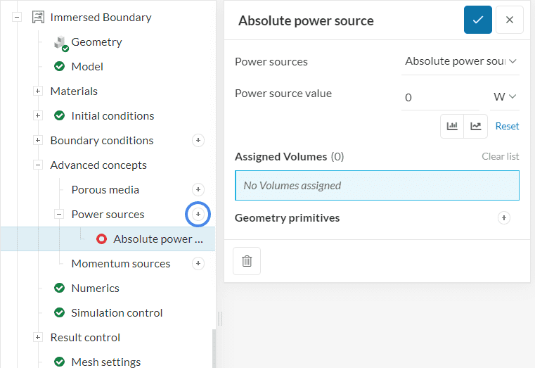
In the simulation tree, navigate to Advanced Concepts and add a Power source by clicking on the ‘+’ button (circled). Absolute, Specific, and Heat Exchanger power sources are supported.
Did you know?
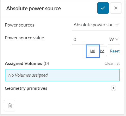
Power sources are supported in parametric studies within SimScale. To define the power sources of interest and run a parametric experiment, you can click on this button:
This article provides more details about the setup of parametric experiments.
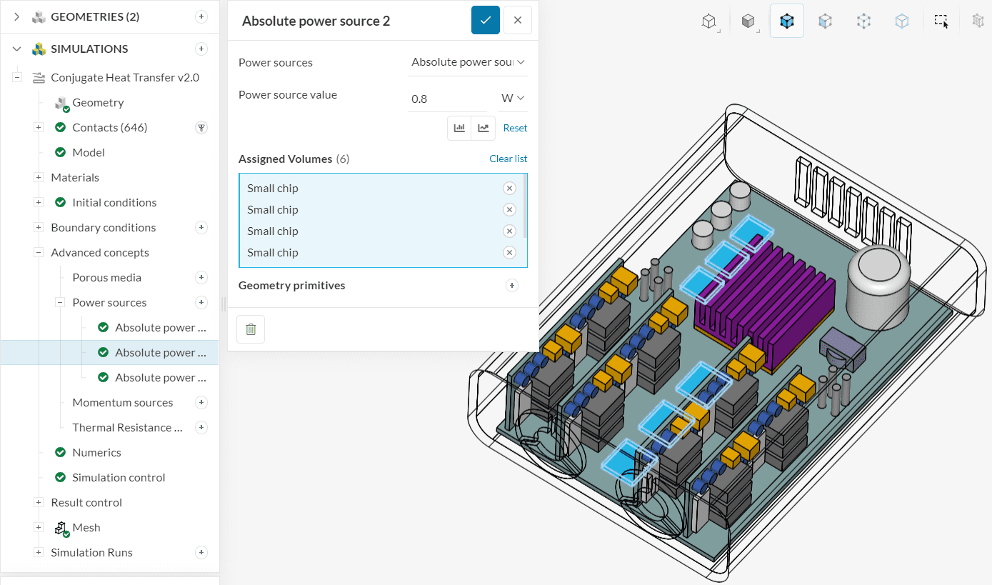
This type of source has to be used when the total power emitted by the heating element is known. The user is required to provide this value and choose the relevant volume region in the domain.
This type of source has to be used when the power density is known. This is simply total power per unit volume in \(m^3\) or \(in^3\). This quantity is often provided for batteries and fuel cells, for example.
Important
If a power source is applied to multiple entities, each of them will generate the prescribed power value. For example, if a heat source with a value of 100 \(W\) is assigned to two entities, each will emit 100 \(W\).
Note
If you assign a negative value to a power source, it will extract heat from the system acting as a heat sink.
This model calculates a power source by comparing the fluid being simulated with the heat exchanger temperature. The main benefit of this power source is that it limits the amount of heat entering the system through the heat exchanger, which is particularly useful for heat sinks and other applications where the amount of heat will not be uniform because it depends on the flow velocity. Two different options are available when using the heat exchanger model. The first one is based on the heat transfer coefficient, while the other is based on the heat exchanger performance. Also, the heat distribution can be modeled based on the local or averaged condition.

The heat exchanger can be modeled by taking into account its heat transfer coefficient, denoted as \(h\ [W/(m^2.K)]\), as well as other properties such as the reference temperature and the surface area density, which is the area divided by the volume of the heat exchanger. The heat transfer coefficient can be input as a table based on the velocity, and the amount of heat transferred will also depend on the velocity.
$$
Q=h(\rho V)\left(\mathrm{T}_{\mathrm{r}}-T\right)
$$
Where \(T_r\ [K]\) is the reference temperature, \(\rho[1/m]\) is the surface area density, \(V\ [m^3]\) is the source term volume and \(Q\ [W]\) is the power source value.
In this model, SimScale will use the total conductance, denoted as \(P\ [W/K]\) rather than the heat transfer coefficient. The only other input required will be the reference temperature. This implies that the model will only need two different parameters to calculate the power source value.
$$
Q=\mathrm{P}\left(\mathrm{T}_{\mathrm{r}}-T\right)
$$
Note
The Heat Exchanger option is only available for the solvers:
Last updated: June 27th, 2024
We appreciate and value your feedback.
Sign up for SimScale
and start simulating now