Structural analysis is the evaluation of the effects of pressures on material structures and their respective elements. This type of analysis uses applied mechanics, applied mathematics, and materials science to estimate a structure’s deformations, stresses, internal forces, support reactions, and overall stability. The results of structural analysis verify the integrity of a structure and are a key part of the engineering design process.
Structural Analysis Types
At SimScale, we chiefly perform 3 types of structural analysis, including static, dynamic, and frequency. In both static and dynamic analysis types nonlinearities can be included. Nonlinearities consist of the plasticity of the material, meaning they account for large deformations, separating contacting, and plastic hyperelastic creep.
Static Structural Analysis
A static analysis considers static load, or steady-state loading, generally used for determining stresses and strains caused by forces that do not create notable inertia or damping effects.
Dynamic Analysis
As opposed to static analysis, dynamic analysis looks at transient loading including forces that change over time, also taking into account inertia. The article’s featured case study will use this analysis type to evaluate the structural integrity of headphones.

Frequency Analysis
Lastly, frequency analysis uses FEA software to find the different natural frequencies of a structure. To learn more about natural frequency analysis, check out this blog that uses FEA and CFD collaboratively to analyze structural integrity.
What Is Engineering Stress and True Stress?
One of the main goals of structural analysis is to determine the stress exerted onto the structure in question. To further define stress, one should consider true stress and engineering stress as two separate, but similar, metrics. To calculate true stress, you take into consideration the change in the cross-sectional area due to elongation forces. Engineering stress does not take the change into account, and only takes the original cross-sectional area of the structure. In the following simulation project, the true stress is evaluated.
Case Study: Dynamic Impact Analysis of Headphones
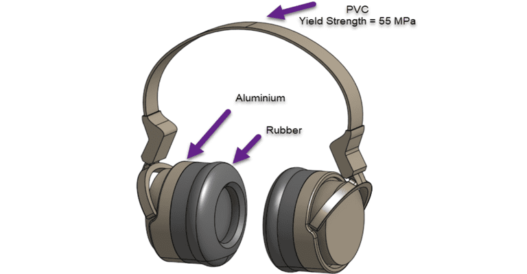
The cloud-based FEA project evaluates the dynamic impact of stress and deformation exerted on a pair of headphones dropped from a height of 1.7 m via a drop test. After assessing the stresses, a geometry change is made and the simulation is run once again to determine how to mitigate design faults in the form of breakage. This impact analysis aims to answer one important question: Will the PVC (Poly Vinyl Carbonate) component break or deform?
The purpose of a helmet is to protect the person who wears it from a head injury during impact. In this project, the impact of a human skull with and without a helmet was simulated with nonlinear dynamic analysis. Download this case study for free.
Simulation Setup: Conditions and Modelling
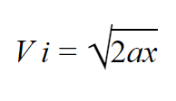
The headphones are dropped from 1.7 m, and by using the equation displayed above we can calculate the impact velocity of 5.775 m/s. Once the impact velocity is established, the time step is the next important factor that must be considered. Time steps should be small enough to capture full detail of the impact and capture the peak stresses. This can be calculated by using the impact velocity (5.775 m/s) and the modeled gap distance (which is set to 18 mm for this simulation). Therefore, dist/Vi (O.018/5.775=0.00312 [s]) equates 0.001 [s] as a sensible time step.
Need some meshing tips? Check out this blog post!
Finite Element Analysis: Plastic Deformations and Geometry Modification
The initial simulation found significant stress on the PVC, particularly in 2 distinct pain points where the stresses were found to be greater than the yield (55MPa). The resulting effect of this could cause plastic deformation and even snapping of the component. The post-processing showed that CAD modification was needed.
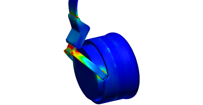
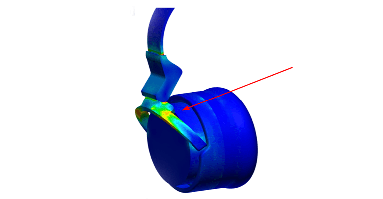
The CAD was then modified to include more mass at the fragile elbow of the connecting components. This added more stiffness and strength to the structure. Only one stress pain point was selected for modification, to provide an example for future alterations that could be possible, as well as provide localized result improvement based on that modification.
Conclusion
After the CAD modification, some stress was still visible via post-processing, however, it was much lower than the stress found in the initial design version. The final level of stress found would most likely not lead to plastic deformation. When stress becomes known through FEA and impact analysis, risk should be mitigated through further design iterations to carry out the products’ longevity.
Watch the recording of our recent webinar on the same topic by filling out a short form here and check out our published slide deck for more information.

