Snap-fits are everywhere you look! Remember your indestructible Nokia 1200? It made use of a very well designed snap-mechanism to ensure the device safety through repeated falls (it also survived the acid attacks inside a fish, but that’s a completely different story). The much-loved children’s toys Lego? Snap-fit mechanism. Belt buckles. Food cans. Be it camera covers, car production, a simple battery case for a remote, or even a huge rocket; everywhere we look, we are surrounded by this marvel of engineering.
The question on everyone’s mind now is, why does this omnipresent mechanism break so easily on some bodies, and lasts decades in others? How can you, as a designer or an entrepreneur, ensure customer satisfaction by using a better snap-fit design?
The answer lies in engineering simulation, and particularly FEA.
What Engineering Simulation Brings
Product design is a highly complex process, with multiple objectives, requirements, and constraints, all of which need to be satisfied for the final product to be successful. The important factors that the designer needs to keep in mind include aesthetics, functionality, cost-efficiency, durability, and safety. While the aesthetic appeal of a product is not quantifiable, the other design aspects are; and they can be accurately tested.
In the traditional design process, the initial design is derived from best practices and past experience—which limits creativity and leaves little room for radical innovation. Coming up with a truly new, ground-breaking design, without relying on best practices, however, is risky and can lead to poor performance. The only way to ensure the durability of such a product is to perform a high number of design iterations until all the criteria are met. Traditionally, that means a high number of physical prototypes and a time-consuming and expensive physical testing phase.
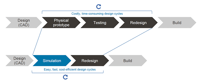
Of course, physical testing cannot (and should not) be eliminated from the product design process entirely. However, multiple prototype building cycles—which account for the bulk of financial and time costs—can be easily avoided by integrating virtual simulation into the workflow. With computer-aided engineering (CAE), you still have an iterative design process, but the days, weeks or months of physical testing are replaced with hours or sometimes even minutes of a simulation run.
When Should Simulation Be Considered
Employing simulation at the right stage of the product development process is another important decision for the designer.
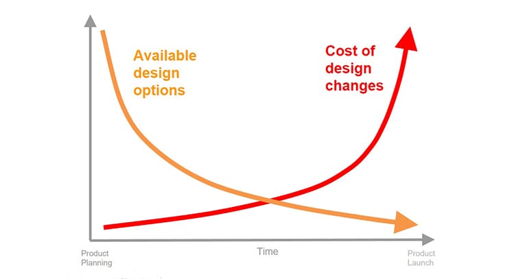
It is important to keep in mind that the closer to the product launch, the more costly design alterations become, due to the increasing number of dependencies in the design. At some point, implementing minor changes and improvements is simply no longer cost-effective. With simulation, on the other hand, these design changes can be implemented even before the first prototype is built, allowing iteration on the design from the very beginning of the development process. This can potentially result in lower costs, minimized failure risks, lighter design, improved performance and user experience, and increased product lifetime.
So Why Isn’t CAE an Industry Standard Yet?
Despite all the advantages mentioned above, several barriers have prevented more engineers and designers from integrating simulation into their design process. Here’s how SimScale is aiming to change this:
- Accessibility (upfront investment). Traditional software needs to be installed locally and needs a significant amount of computing power. That means highly expensive hardware, that stands idle while the simulations are running. With SimScale, all computations are done in the cloud and require no local installation—just a standard web browser.
- Operating costs. High licensing costs for standard commercial tools put them out of reach for many designers. SimScale starts with a free Community plan with an option to upgrade to an affordable Professional subscription.
- Know-how. Current CAE tools are not too user-friendly and are designed for CAE experts. This expertise gap can be minimized with intuitive UI, large public project templates library, live support chat, and free training material. Any of the public projects can be imported into the workspace, and once can simply exchange the CAD model, reassign the boundary conditions, and run the simulation without having to know too much about simulation upfront.

Example Study: Smarter Snap-Fit Design Using FEA
The snap-fit design depends on the expected use and life, and can hence vary substantially. Cantilever snap designs are known to be the most common, and the “U” or “L” shape snaps are very popular as well. The design factors to be kept in mind include the shape of the snap, the thickness of the beam, and the ratio of the thickness to the beam length. Optimizing the design of a snap body is a challenging process, and a lot of information regarding the stresses on the body can be obtained from simulations. One can use the information obtained to determine the life cycle of the snap, how much load it can sustain, and under what conditions. This knowledge can be used to determine the expected lifecycle of the part, the different stress concentration regions, and even be used to determine the manufacturing process itself.
Traditionally, engineers have relied on experimentation and physical testing to ensure the reliability of their snap-fits. Yet in addition to being expensive and time-consuming; identifying all stress points through experimentation is highly challenging and the designer risks missing critical information. Simulation simplifies the data analysis necessary to make informed design decisions while saving time and money, and as a result delivering a more reliable product to the market much faster.
In this webinar, we discuss how to make a better snap-fit design. How to ensure that the least possible material is used, and the longest life-cycle achieved, as well as what goes on behind the scenes for ensuring a snap-fit will last forever or break right after the warranty runs out.
Find out how an extraordinary engineering marvel can still be improved with cloud-based simulation, and how it can help you become a better designer!
Project Overview
The project used in this webinar session is publicly available in the simulation project library—feel free to copy and modify it: Finite Element Analysis of a Snap-Fit.
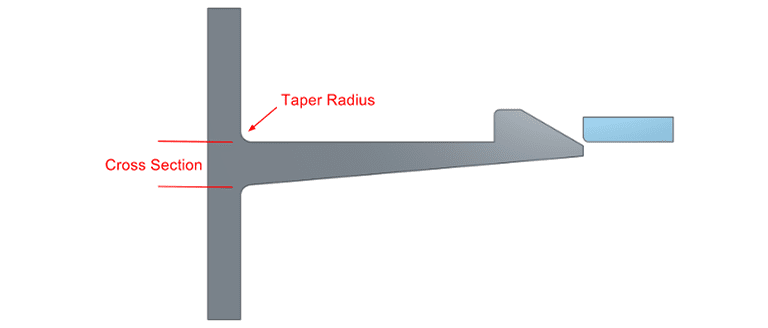 Snap-fits come in a wide variety of shapes, sizes, and materials. There is no one-design-suits-all—how well the snap-fit design will perform in real life depends heavily on the intended application. Therefore, in order to approach the problem of optimizing its design, the following design parameters need to be determined:
- Material
- Cross section shape
- Constant
- Varying
- Cross section type
- Cantilever snap joints
- U-shaped snap joints
- Torsion snap joint
- Annular snap joints
- Taper radius
Once all the information is obtained, the simulation setup can proceed. The results can be used to validate the solver for snap-fit design simulations by comparing them to the experimental data presented in the Bayer Material Science paper [1].
After setting up the CAD model, meshing can commence. The mesh defines the accuracy of the result. It should only be fine at the areas of interest: initially, it can be coarse all over, but subsequently, refinements to the areas of interest need to be provided based on the results.

The snap shall be given a displacement boundary condition. The small box against which the body deforms shall be given a fixed boundary condition. Using symmetry conditions allows the decrease of the number of nodes, the increase of the convergence speed, and the reduction of the model size.
Simulation Results
Areas undergoing the highest stress are clearly visible in the simulation results—the snap deforms and snaps into place. This CAD model is already fairly well-designed, with the snap end being tapered, and hence the strain on the final body is not excessive.
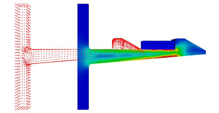
Without this taper, however, the strain on the snap would be much higher, causing an earlier breakdown and hence limiting the lifetime of the snap.
For comparison, the initial (points) and the final (solid) positions of the snap body can be seen in the image to the right.

If these results are compared to the ones presented in the paper, it can be seen that the mating force and the maximum deflection of the snap seen in the simulation closely match the experimental values. The minor difference in results can be attributed to the meshing grade and can be fine-tuned later.
Conclusion
Looking at the results of this simulation, it becomes evident that a proper snap-fit design is essential for ensuring low-stress concentration at points of contact, taper points, and at the deflecting face. A snap-fit has significantly more stress near the deflecting face (head) than on the tail of the deflecting snap. Most importantly, it was discovered that, compared to the snap-fit design with a constant cross-section, a tapered snap has lower stress values (can undergo more cycles) and a longer life (increased durability), and uses less material (cost saving).
In this case, we investigated leveraging FEA to design smarter snap-fit mechanisms—but this is just one example of how designers and engineers can apply simulation tools in the product development process. The SimScale Public Projects library has a wide selection of templates simulating various product use conditions across multiple industries, including automotive, aerospace, machinery, electronics, and HVAC.
Explore it by creating a free Community account.
Discover all the simulation features provided by SimScale. Download the document below.
References
- Snap-Fit Joints for Plastics, Bayer Material Science: https://fab.cba.mit.edu/classes/S62.12/people/vernelle.noel/Plastic_Snap_fit_design.pdf


