The strength of each individual component can determine the product’s performance lifecycle, and, when designed improperly, can potentially cause failure. That is especially true for tractors and other agricultural equipment, which are used in rough terrain and under tough conditions. Immense forces are created when such heavy equipment is in operation. The machinery must also be strong and reliable enough to endure additional loads resulting from a mistake on the part of the operator. Those loads can cause the tractors to operate outside of their normal operating conditions. Accounting for such loading and designing a safe and reliable machine is the task of the engineer—and here’s how this task can be made easier.
To illustrate how finite element analysis or structural mechanics simulation helps engineers predict the behavior of heavy equipment under different operating conditions, we hosted a free 30-minute webinar on December 5, 2017. Watch the recording.
How Can You Benefit from Simulation?
Manufacturing of heavy equipment is a capital-intensive process, putting pressure on design engineers to ensure the safety and reliability of their designs before investing in physical prototyping and manufacturing. Companies also face a growing number of new requirements that their products need to meet, while at the same time trying to dramatically reduce the time it takes to bring the machine to market.
All this requires you, as a design engineer, to continuously innovate, test, and optimize your designs to be able to deliver high-quality, performant heavy equipment to your customers around the world. In the traditional design process, the only way to ensure the durability of your design is to perform a high number of iterations until all criteria are met. This implies a high number of physical prototypes and a time-consuming and expensive physical testing process.
Integrating simulation into your development process can help you drastically reduce the development time and costs, not only by replacing physical prototyping and avoiding numerous iterations but also by helping you reach the final design version earlier. After all, the earlier in the overall process, the more cost-effectively a design change can be realized. At a later stage, the scope of possible improvements narrows drastically, with only small, incremental design modifications possible.
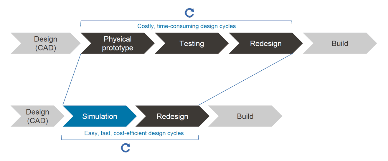
Of course, physical tests cannot (and should not) be entirely eliminated from the product design process. Physical and virtual prototyping are not mutually exclusive—they are complementary. But with computer-aided engineering (CAE), the days, weeks or months of physical testing turn into hours or sometimes even minutes of a simulation run.
Why SimScale?
Why aren’t all designers using simulation yet? Several barriers have prevented a more widespread adoption of simulation tools by engineers and designers—and here’s how SimScale is aiming to challenge this status quo:
- Accessibility: Traditional software needs to be installed locally on expensive high-performing computers, most of which remain idle most of the time. With SimScale, all computations are cloud-based—all you need is a web browser.
- Operating costs: Standard commercial simulation software packages are notoriously expensive. With SimScale, there is an option to start simulating right away with a free Community Plan.
- Know-how: Most modern tools are designed for experts and experienced simulation engineers. To bridge that knowledge gap, SimScale offers a large public projects library, free training, and live support chat.
Engineering Problem: Strength Analysis of Heavy Equipment (Tractor Loader Arm)
In this case study, we will illustrate how to leverage simulation to achieve the following goals:
- Compare both designs of the loader arm with respect to structural strength for operational and misuse loads.
- See if any of the designs undergo permanent deformation under these loading conditions (yield limit 250MPa).
- Find out if any of the designs have a factor of safety less than 2.
We will use the following simulation project as a template for our analysis: Strength Analysis of a Tractor Loader Arm.
Simulation Setup
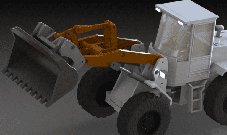
For the simulation, a symmetrical model was used to save computational time. Seven sliding contacts boundary conditions were created. One displacement constraint was used to generate the symmetry plane. For the connection of the arm with the two hydraulic cylinders and the chassis, remote displacement boundary conditions were created. The load was then applied with a remote force. The first three simulation runs were performed with a 16kN load, which is the normal operating load for this class of tractor (JCB Backhoe Loader). Then three additional runs were performed with a misuse load of 20kN, which would occur if the operator tries to load an extra 400kg in the shovel.
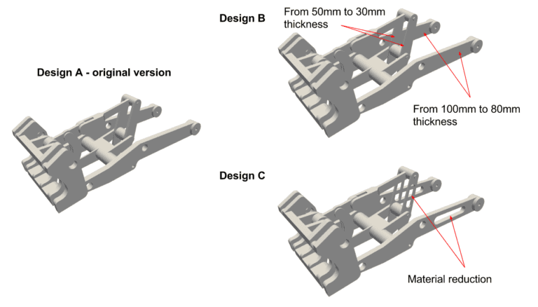
For each load, the performance of three different designs was tested:
Design A: Original design downloaded from GrabCAD;
Design B: Changes in thickness, as in the picture below; and
Design C: Design B with additional material reduction.
Results
The simulation allows one to accurately predict and estimate the loads for each of the studied cases. The von Mises stress for each case is shown in the table below:
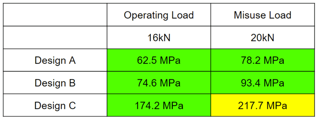
From these results, we can conclude that:
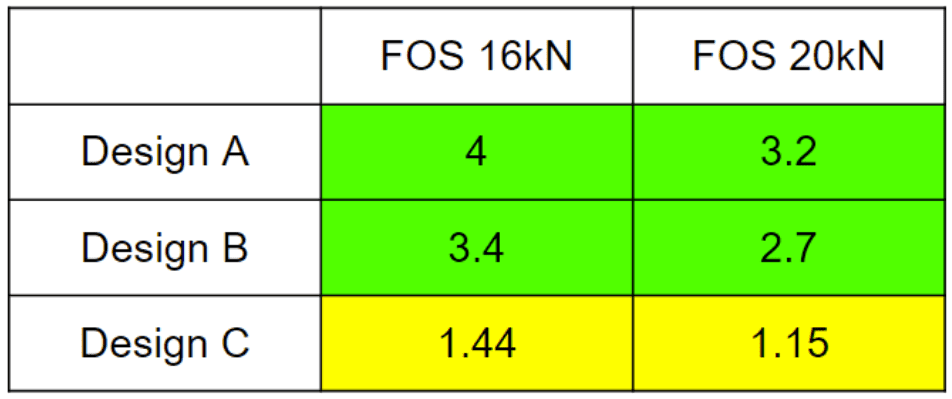
- Design A and B passed the misuse loading simulation;
- Design C is close to the yield limit (250 MPa) for the misuse loading. A further assessment is necessary to determine if the frame can be approved.
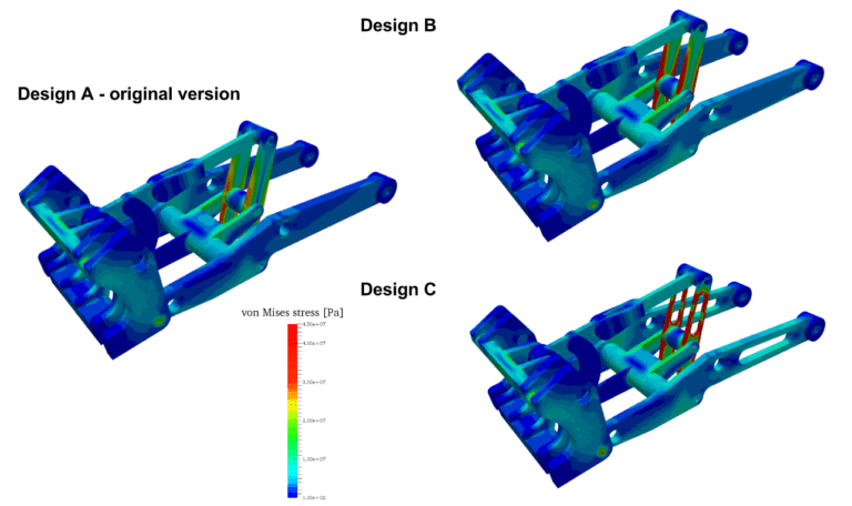
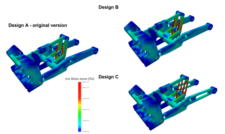
It is clear from the results that the design can be improved, as it didn’t reach yield stress for any of the cases—not even Design C under misuse load, which was the most aggressive in terms of material reduction. Of course, this will always be a compromise between the design and its factor of safety (FOS). There will be a limit to how much we can reduce the material while ensuring the desired FOS.
Further Design Alternatives to Consider
The results above indicate that the loader arms have not reached plastic deformation, but it can be seen that, especially for the misuse load, Design C gets a FOS of 1.15, which can be considered too low for a tractor. From that, it can be concluded that a new design can be proposed and investigated, where material and weight can be reduced while maintaining the FOS at a higher value. This can be achieved through several potential design changes, the effectiveness of which can also be tested with the aid of simulation.
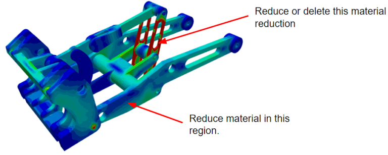
1. Reduce the material reduction in the red area and add a new reduction to a blue area. It should increase the FOS.
2. Use a higher-grade material with an increased yield point. Your choice of material will definitely impact the project’s budget so it should be selected carefully.
Conclusion
Every company in the agricultural or heavy equipment sector designs equipment capable of reliable performance under a wide range of operating conditions, even when the operator makes a mistake. Simulation is now becoming an essential element of the design process, giving engineers confidence to quickly and cost-effectively develop the robust equipment that the market demands.
This is just one example of how FEA tools can help designers or engineers evaluate their design. The SimScale Public Projects library has a wide selection of simulation templates covering various aspects of industrial equipment and machinery (heavy equipment/construction equipment, plant machinery, machine tools, cutting tools and rolling machines, industrial robots and packaging machinery), manufacturing (stamping processes, molding and forming, fastening systems), and many more.
Explore them by creating a free Community account. Watch this free webinar to learn more:

