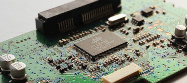
An integrated circuit (IC), often referred to as a microchip, microelectric chip, or simply chip, is a set of electronic circuits fabricated on a single, small, flat piece of semiconductor material, typically silicon. It combines thousands or even millions of transistors, diodes, and resistors onto a single chip.
ICs are fundamental to all microelectronic designs (in smartphones, laptops, industrial automation, medical devices, aerospace systems, etc).
Efficiency, reliability, and thermal management are at the heart of integrated circuit design, as they directly influence the performance and lifespan of the chip. A well-designed IC must balance power usage, maintain consistent operation, and effectively dissipate heat to avoid failures or degradation.
Key Components of Integrated Circuit (IC)
Integrated circuits function by leveraging the collaborative roles of their key components—transistors, resistors, capacitors, and diodes—on a compact silicon substrate.
In digital ICs, transistors toggle between on and off states to process binary data, while in analog ICs, they amplify or modify signals for precise output. Their rapid switching capability and scalability make transistors the driving force behind the IC’s functionality.
Resistors adjust signal levels and protect sensitive components by limiting current. Capacitors, on the other hand, store and discharge electrical energy, playing a critical role in filtering noise, smoothing power supply variations, and enabling signal timing adjustments. Diodes contribute by directing current flow and managing signal modulation.
In complex printed circuit boards (PCBs), components like transistors, resistors, capacitors, and diodes are arranged across multiple layers to accommodate high-density interconnections and optimize performance.
Thermal management through thermal vias (plated holes that transfer heat from hot layers to cooler ones) and heat sinks prevents overheating.
Types of Integrated Circuits and Key Components
Integrated circuits can be functionally classified into three main categories: digital, analog, and mixed ICs. Each type serves specific operational needs and applications.
Digital Integrated Circuit
Digital ICs process discrete signals, working exclusively with binary data—0s and 1s. They are ideal for computational tasks, logic operations, and data storage. Below are some of its applications:
- Microprocessors and microcontrollers
- Memory units (RAM, ROM, Flash)
- Logic gates and digital signal processors (DSPs)
- Embedded systems and IoT devices
- Communication systems (e.g., routers, switches)
Analog Integrated Circuit
Analog ICs operate with continuous signals, amplifying or processing voltage and current for applications. They offer precision and adaptability in translating natural phenomena into usable electronic signals. Here are some common applications:
- Audio amplifiers and signal processing devices
- Power management systems (e.g., voltage regulators)
- RF circuits in communication systems
- Medical instrumentation (e.g., ECG amplifiers)
Mixed Integrated Circuit
Mixed ICs combine digital and analog functions within a single chip, enabling complex tasks like analog-to-digital conversion (ADC) and digital-to-analog conversion (DAC).
While their hybrid nature delivers unmatched functionality, it also makes them more complex and cost-intensive to design and manufacture. Applications include:
- Smartphones and wearable devices
- Automotive systems (e.g., infotainment, sensors)
- Industrial automation and control systems
- Communication modules integrating RF and digital processing
Design Principles and Challenges in IC Design
IC design demands precision, with thermal management a critical priority to ensure performance and reliability. Here are five key factors to consider:
1. Power Management
Effective power management in ICs requires precise regulation and distribution to maintain stability and efficiency. Integrated voltage regulators ensure consistent supply levels, safeguarding transistors and logic gates from transient fluctuations that could disrupt operation.
Power and ground planes within the PCB layout provide low-impedance paths to handle current flow while minimizing noise.
Decoupling capacitors, strategically placed near active components, filter high-frequency noise and stabilize voltage at critical nodes.
2. Signal Integrity
In IC design, electric signals should maintain their quality and timing as they propagate through the circuit. High-frequency designs demand precise control over propagation delays to prevent timing mismatches that can disrupt functionality. Here are some common considerations:
- Crosstalk, a common issue in tightly packed layouts, should be minimized by careful spacing and using ground planes to isolate signal paths.
- For clock signal distribution, skew reduction techniques such as matching trace lengths and impedance are critical to maintaining synchronized signal timing across the circuit.
- Low-dielectric/highly conductive materials are increasingly used in interconnects to minimize resistive losses and ensure sharp signal transmission.
3. Thermal Management
Excessive heat buildup can cause shifts in operating parameters, degrade components, and even lead to complete failure. Poor thermal management risks damaging sensitive parts and forcing the system to operate outside its designed temperature range.
Engineers dissipate the heat efficiently to keep the operating temperature within safe limits. A low thermal resistance ensures better heat transfer, keeping the IC cooler during operation. Operating temperatures of the IC materials are designed to stay within specific limits.
PCB passive cooling mechanism has become an integral design choice. By integrating thermal vias and copper planes into the board layout, the PCB dissipates heat away from hotspots and distributes it across the layers. It reduces the dependency on external heat sinks or active cooling systems while maintaining the compact footprint required in modern IC designs.
External heat sinks remain a standard solution, especially in applications where high power density demands active heat dissipation.
Heat pipes are also a solid option for moving heat fast in compact systems. They work by transferring heat from the source to a cooler area using phase-change materials. For even more control, Peltier effect cooling plates can pull heat away directly using thermoelectric technology.
4. Miniaturization
The goal is to create smaller, more compact IC designs while maximizing power output—a concept known as power density. Careful optimization of the form factor (physical dimensions, shape, and layout) ensures the IC delivers high performance without increasing its physical footprint.
Compact designs are particularly critical in applications like portable electronics, IoT devices, and advanced computing systems, where space constraints are non-negotiable.
5. Durability
Mechanical stresses, such as those caused by temperature cycling, vibration, or physical impacts, can lead to microcracks in the package or bonding wires. Thermal stresses accelerate material fatigue and degrade the performance of critical components.
Electrical stresses, including voltage spikes and power surges, can push the IC beyond its operating limits, leading to breakdowns in transistors or interconnects.
Durability also involves optimizing the PCB layout and package design to distribute stress evenly and reduce localized strain.
The Role of Simulation in Integrated Circuit Design
Simulation enables engineers to create compact, high-performance circuits with greater precision than traditional validation methods. Engineers can simulate complex IC designs to manage thermal performance, minimizing hotspots and ensuring signal integrity.
SimScale offers a powerful yet accessible platform for IC design. Its thermal management software is particularly effective for applications where heat and energy are critical, such as PCBs with anisotropic material properties. It also supports thermomechanical analysis with multiphysics capabilities to evaluate stress and deformation caused by thermal expansion.
Engineers can run multiphysics simulations within minutes, combining thermal and structural analysis. It helps them identify potential hotspots and predict how these areas could impact the overall durability of the design.
IC Design Optimization in the Cloud
Cloud-based simulation tools, like SimScale, provide engineers with powerful capabilities to analyze and refine their designs using transient thermal analysis.
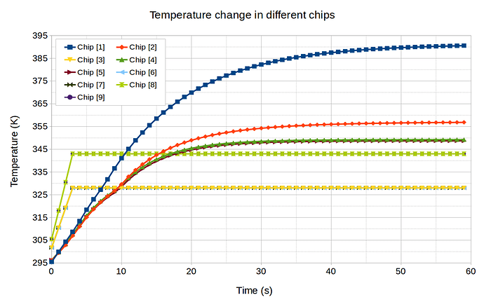
In a recent PCB design study in SimScale, nine chips were tested under varying conditions to observe how temperature and heat flux changed over time. For five chips, temperature changes were mapped by uploading time-dependent data tables, while the remaining chips had surface heat fluxes modeled similarly.
These images illustrate how temperature evolves over time in a PCB thermal simulation.

The next two images depict how surface heat flux varies over time.


These simulations allowed engineers to visualize temperature distributions on both the top and bottom of the PCB, offering insights into how heat flows through the system over time. The results highlighted areas requiring design improvements, which were integrated into the CAD model and re-tested iteratively until optimal performance was achieved.
Conclusion
Effective IC design means creating functional components while adapting to ever-shrinking form factors and rising demands for reliability.
SimScale allows engineers to predict and resolve challenges before they become costly mistakes.
Start simulating today with SimScale. No installation or credit card required.
Main Contributor: Muhammad Faizan Khan


